How Much Do You Know About Inverter Controlled Motors?
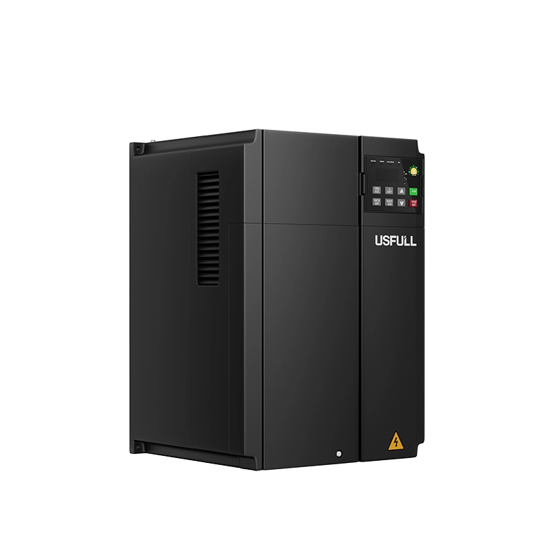
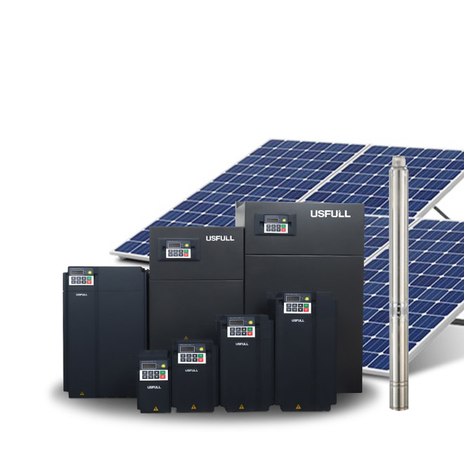
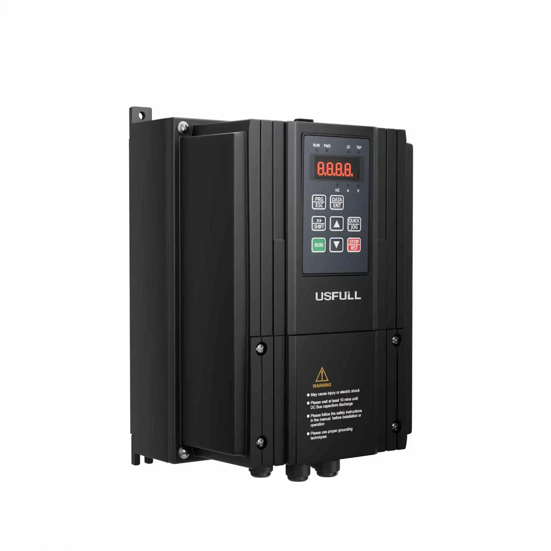
Frequency inverters, also known as variable frequency drives (VFDs) or variable speed drives, are pivotal in modern motor control. They allow for precise control of motor speed by adjusting the frequency of the electrical power supplied to the motor. Whether it’s a small fan or a large industrial washing machine, these inverters play a crucial role in enhancing energy efficiency, extending motor life, and enabling smoother operation. But how well do you understand the capabilities and adjustments possible with a frequency inverter?
Why Use a Frequency Inverter to Control a Motor?
First, let’s briefly understand the two components involved: the motor and the frequency inverter.
Motors are inductive loads that resist changes in current. When starting, they can cause significant fluctuations in current. A frequency inverter is a device that uses semiconductor switching to convert a fixed frequency power supply into a variable frequency output. It mainly comprises two circuits: the main circuit (including the rectifier module, electrolytic capacitor, and inverter module) and the control circuit (consisting of a switching power supply board and control circuit board).
One of the primary benefits of using a frequency inverter is its ability to reduce the starting current of the motor, which is especially crucial for larger motors. Larger motors draw a higher starting current, which can strain the power supply network. A frequency inverter solves this problem by allowing the motor to start smoothly without causing an excessive current surge.
Another key function of a frequency inverter is speed control. Many industrial processes require precise control of motor speed to achieve optimal efficiency. By adjusting the frequency of the power supply, the inverter VFD can control the motor’s speed, making it one of the most valuable features of these devices.
What Are the Frequency Inverter Control Methods?
There are several methods to control a motor using a frequency inverter. The most common ones include:
U/f = C Sinusoidal Pulse Width Modulation (SPWM) Control Method
This method is characterized by a simple control circuit structure and low cost. It maintains a constant voltage-to-frequency ratio, which ensures smooth speed regulation in most applications. However, at low frequencies, the output torque decreases due to the impact of the stator resistance voltage drop. Additionally, the mechanical characteristics are not as rigid as those of a DC motor, leading to slower torque response and reduced stability at low speeds.
Voltage Space Vector (SVPWM) Control Method
SVPWM is designed to approximate an ideal circular rotating magnetic field in the motor air gap by generating three-phase modulation waveforms. This method has been refined with frequency compensation to eliminate speed control errors and improve dynamic precision and stability. However, it involves more control loops and does not inherently adjust torque, so the overall system performance may not be fully optimized.
Vector Control (VC) Mode
Vector control converts the motor’s three-phase stator currents into two-phase stationary or rotating reference frames. This method allows for independent control of motor speed and magnetic flux, mimicking the control method of a DC motor. Although vector control has revolutionized motor control, it can be challenging to implement due to the complexity of accurately observing the rotor magnetic flux and the sensitivity to motor parameter variations.
Direct Torque Control (DTC)
DTC was first introduced in 1985 and has since become a popular control strategy due to its simplicity and superior performance. Unlike vector control, DTC does not require the complex vector transformations and directly controls the motor’s torque and flux. This method is known for its fast torque response and high efficiency.
Matrix Cross-Cross Control Method
Traditional methods like VVVF, vector control, and DTC belong to the AC-DC-AC conversion category. However, they share common drawbacks, such as low input power factor, high harmonic currents, and the need for large energy storage capacitors. Matrix converters eliminate the intermediate DC stage, allowing direct AC-AC conversion. This method can achieve a high power density, sinusoidal input currents, and four-quadrant operation, making it a promising area of research.
How Does a Frequency Inverter Control a Motor? How Are the Two Wired Together?
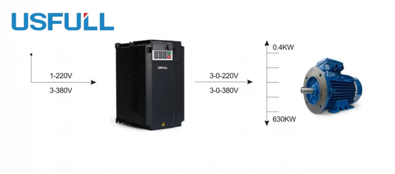
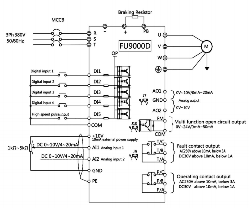
Wiring a frequency inverter to a motor is relatively straightforward, similar to wiring a contactor. The inverter connects to the motor via three main power lines, but the settings and control methods vary widely.
Most inverters have terminals for switch inputs that control the motor’s forward and reverse rotation, feedback terminals that monitor the motor’s operating state (such as frequency, speed, and fault status), and speed-setting controls, which can be adjusted using a potentiometer or buttons. Additionally, many modern inverters support communication control, allowing the motor’s start, stop, direction, and speed to be controlled and monitored via a communication network.
What Happens to the Output Torque of a Motor When Its Rotational Speed (Frequency) Changes?
When a motor is driven by a frequency inverter, the starting torque and maximum torque are usually lower than those achieved with direct mains power. The direct mains power start causes significant current surges, while an inverter gradually increases the output voltage and frequency, resulting in lower starting currents and reduced mechanical stress.
Typically, as the frequency decreases, so does the torque. The exact reduction is often specified in the inverter’s manual. However, using an inverter with flux vector control can improve the motor’s low-speed torque performance, ensuring sufficient torque even at low speeds.
When the frequency exceeds 50Hz, the motor’s output torque decreases in proportion to the frequency. This is because the motor is designed to operate at a specific voltage-to-frequency ratio, usually based on a 50Hz power supply. Operating above this frequency requires the motor to work in a constant power mode, where the torque decreases as speed increases.
Application of Frequency Inverter Above 50hz
Operating a motor at frequencies above 50Hz can be beneficial in certain applications where higher speeds are required. However, it is crucial to ensure that the motor and the mechanical components can handle the increased speed without incurring damage. In such cases, the frequency inverter must be carefully programmed to ensure that the motor operates within safe limits while still achieving the desired performance.
What Is the Appropriate Frequency for a Frequency Inverter to Control a Motor?
The appropriate frequency for controlling a motor with a frequency inverter largely depends on the specific application and the motor’s design. For most standard motors, the frequency range of 0 to 50Hz is typically used for general operations. However, in specialized applications, the frequency can be adjusted above 50Hz, as long as the motor is rated for such operation. The key is to balance performance requirements with the motor’s capability to handle the varying speeds and torque.
In summary, when applying variable frequency drive (VFD) technology to induction motors for over-frequency operations, it’s crucial to consult the motor manufacturer to determine feasibility or to consider custom motor solutions to ensure reliability at high speeds. If working independently, start by conducting dynamic balance testing on the rotor and verifying the bearing’s maximum speed; if limits are exceeded, high-speed bearings should be used to meet operational demands. Additionally, heat dissipation must be considered. Based on experience, for induction motors operating below 100Hz, those with a power rating under 100kW are generally acceptable, while motors above 100kW should ideally be customized rather than relying on standard products.

