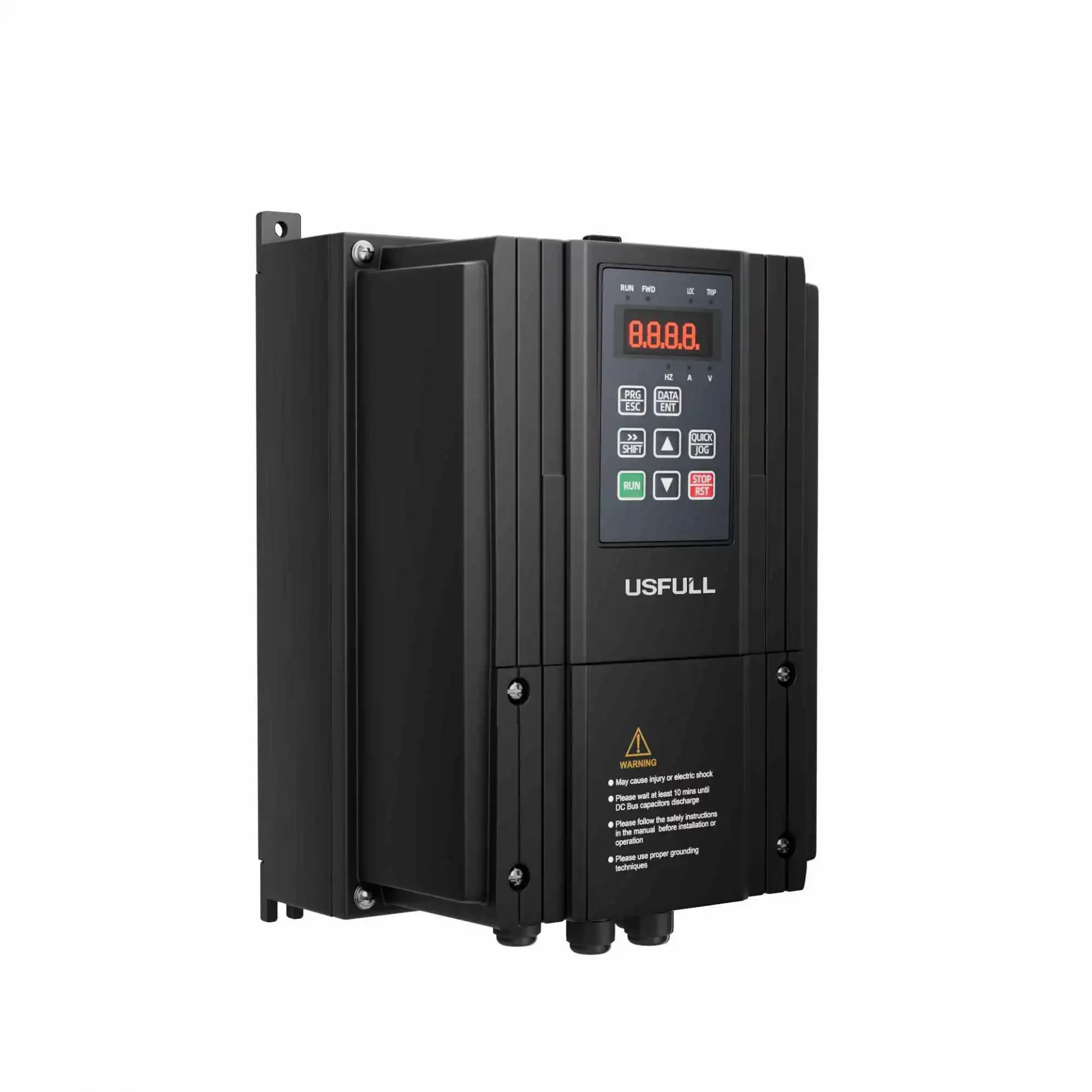
When operating a frequency inverter or variable frequency drive (VFD), accurately displaying current values is crucial for maintaining system efficiency and preventing malfunctions. However, errors in the current display can arise due to improper sampling, inaccurate measurement devices, or external factors. Below are key solutions to resolve these issues:
1. Changing the Current Transformer Mounting Position
One of the primary causes of current display errors is the mounting position of the current transformer. Moving the sampling point from the inverter input side to the output side is often recommended.
- Input vs. Output Current Characteristics:
While input current contains high-frequency harmonics and pulsed waveforms, the output current of a variable frequency inverter is closer to a sine wave, thanks to sinusoidal pulse-width modulation (SPWM). This alignment reduces measurement discrepancies. - Improved Accuracy:
Measuring the output current better reflects actual motor conditions, minimizing errors. Furthermore, any necessary adjustments can compensate for residual discrepancies caused by harmonic distortions.
2. Selection of Ammeter
The choice of ammeter significantly impacts the accuracy of current measurement. Several factors should be considered:
- Traditional vs. Modern Tools:
Electromagnetic current meters are recommended for measuring effective current values with harmonic components. Although they are less accurate for low current levels, they are cost-effective. - Field Applications:
For practical use, especially after relocating the transformer to the output side, 1T1 moving iron meters or rectifier-based instruments (with proper compensation) can be employed. A 42L6-A 20/5 rectifier-based current meter, for instance, has been successfully utilized in various inverter VFD
3. Solutions to the Inherent Error of the Current Transformer
Errors stemming from the current transformer itself can be mitigated through specific adjustments:
- Increasing Primary Current:
Adding turns to the primary winding can elevate current to a level where magnetic flux leakage and hysteresis losses are minimized. For instance, a 200/5 current transformer with 13 primary turns can achieve a more accurate measurement ratio (15.385/5).
Maintaining Design Consistency:
Adjusting primary winding does not alter the original transformer ratio, ensuring compatibility with existing system designs. This method has proven effective for addressing harmonic distortions and maintaining long-term stability in variable speed drive applications.
4. Solutions to Current Errors on Field Control Boxes
Transmission distance between the variable frequency inverter cabinet and field control boxes can also introduce errors:
- Local Signal Acquisition:
Installing an additional current transformer within the field control box can reduce transmission errors. By sampling current directly from one phase of the main circuit and displaying it on a 42L6-type ammeter, on-site accuracy improves significantly. - Optimized Cable Use:
Utilizing appropriate cables and minimizing the distance between the transformer and the field box can further enhance reliability.
5. The Main Control Room Current Display Solution
For systems where the inverter VFD is near the motor load but distant from the control room, transmission accuracy is critical:
- Integrated Solutions:
A 200/5 current transformer with 13 primary windings can be installed at the inverter output side. Additionally, incorporating a BS4I current transducer converts high-harmonic current (0–5A) into a 4–20mA DC signal, ensuring compatibility with control room systems. - Signal Isolation for Safety:
A 4–20mA signal isolator (e.g., RZG-2100) separates field and control room signals, safeguarding computer systems from potential interference.
Conclusion
Addressing current display errors in frequency inverters and variable frequency drives requires a combination of hardware adjustments, proper instrumentation, and strategic sampling. By implementing the solutions outlined above, businesses can enhance system reliability and measurement accuracy, paving the way for smoother operations and better system performance.
USFULL, a leading manufacturer of variable frequency drives and related products, is dedicated to offering customized solutions that meet diverse operational challenges. With decades of expertise and a strong global presence, USFULL ensures quality and innovation in every product. Contact us for tailored solutions to your electrical system needs.

