Operational Principle:
The incremental rotary encoder operates by translating the timing and phase correlation of its angle-coded disk via two internal photosensitive receiving components. This translation facilitates the determination of angular displacement alterations, resulting in either positive (incremental) or negative (decremental) changes.
Internal Mechanism (Determining Direction):
The AB phase encoder contains two sets of photocouplers, which generate two distinct pulse sequences with a 90° phase disparity. The pulse sequence’s lead and lag relationships invert themselves when the encoder undergoes forward or reverse rotation.
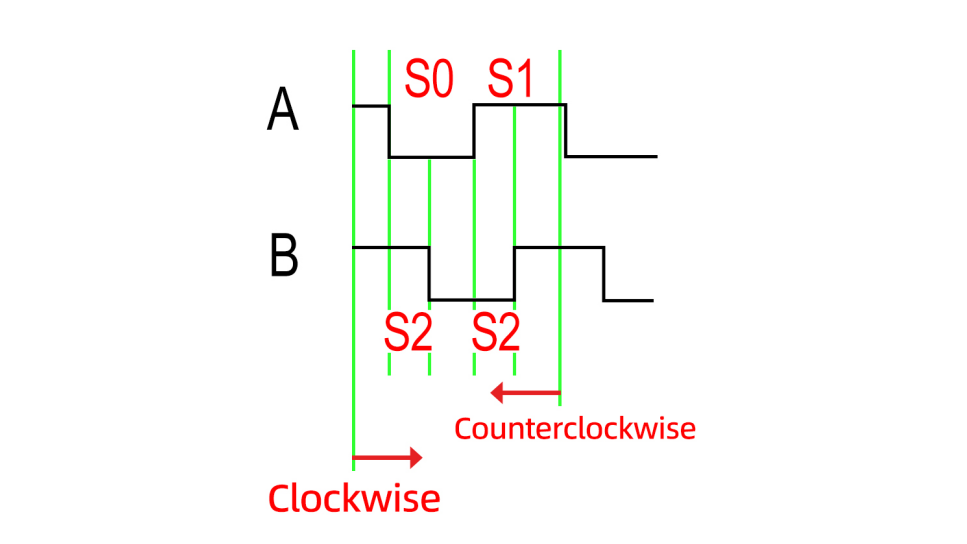
In the context of forward rotation, the A-phase pulse’s polarity contrasts the B-phase pulse’s polarity precisely at the rising edge of the B-phase pulse. In reverse rotation, this polarity contrast remains evident. Thus, employing the AB-phase encoder enables the Programmable Logic Controller (PLC) to readily ascertain the shaft’s rotation direction. Refer to the following schematic:
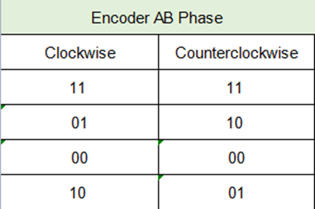
From the table above, the following conclusions can be drawn:
The AB phase codes differ for forward and reverse rotations. Knowledge of the current and subsequent AB phase codes allows the determination of the encoder’s rotational direction.
Distance Calculation:
An acquired encoder features specific parameters: encoder resolution (pulses per revolution) and circumference (circumference of a single rotation).
The distance associated with one pulse = encoder resolution / circumference.
Hence, rotation distance = pulse count * encoder resolution / circumference.
To enhance accuracy and minimize error, it is plausible to employ a fixed-length pulse requirement:
Pulses needed for a fixed length = fixed length * circumference / encoder resolution.
Implementation Approach (STM32 Programming):
This implementation concept necessitates familiarity with STM32 External Interrupts (rising or falling edge interruption).
1. An external interrupt is employed to capture the rising (or falling) edge of phase A or B. This action triggers an interrupt, leading to the entry into an interrupt service routine.
2. The interrupt service routine’s code accomplishes the following: determining the level of phase B or A (used to ascertain forward or reverse rotation).
Illustrative Example:
For the purpose of this example, an interrupt captures phase A’s rising edge.
Upon capturing the phase A’s rising edge, the polarity of phase B is assessed (see diagram).
A low polarity in phase B signifies forward (clockwise) rotation, while a high polarity suggests reverse (counterclockwise) rotation.
Post-directional determination, an incremental adjustment is applied to the relevant pulse formula, subsequently enabling the distance computation.
For velocity calculation, the inclusion of a timer is recommended.
This sophisticated and comprehensive approach ensures accurate measurement and analysis of the incremental encoder’s rotational characteristics, enabling precise motion monitoring and control.