Introduction:
Measuring the output frequency of an inverter is crucial for ensuring optimal performance during actual operation. This value may deviate slightly from the specified frequency signal, necessitating accurate measurement for reference and feedback adjustment. In this comprehensive guide, we will explore various methods to detect the actual output frequency of an inverter, with a focus on both analog and communication-based approaches.
Analog Mode:
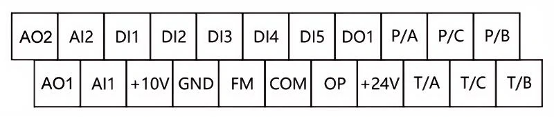
Analog input and output are integral parts of a frequency converter, providing a means to set and monitor the given frequency. The analog input typically involves a DC voltage signal (e.g., 0-10V) or a current signal (e.g., 0-20mA). On the other hand, the analog output conveys operating parameters such as voltage, current, power, and the frequency value to be detected, all presented as analog quantities.
1. Using Analog Instruments:
– Ammeters and voltmeters serve as direct tools to measure the actual operating frequency, providing a visual representation on the meter.
– Digital displays, such as tachometers, convert analog quantities into digital values for convenient and accurate readings.
– Analog-to-Digital (AD) modules and Programmable Logic Controllers (PLCs) collect analog quantities, converting them into digital feedback for precise control. The principles remain consistent across these instruments – the conversion of analog values into actual frequency readings.
2. Setting Output Parameters:
– In the inverter settings, users can select the desired output parameter, choosing between voltage and current signals to represent the frequency value. This flexibility allows for customization based on specific operational requirements.
– For instance, a voltage signal of 10V might correspond to a maximum frequency value of 50Hz. The proportional relationship enables the conversion of analog signals into meaningful frequency readings. For example, an output frequency corresponding to 2.5V might be interpreted as 12.5Hz.
Communication Method:
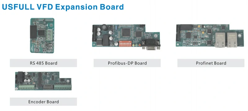
While more challenging, the communication method offers simplicity in wiring and facilitates convenient numerical collection without the need for additional conversion. Modern frequency converters often support communication control, enabling real-time data collection alongside operational control. Several communication methods are available, including MODBUS, PROFIBUS, and PROFINET, depending on the inverter’s capabilities and compatibility with the host computer.
1. MODBUS Communication:
– Economical and general-purpose inverters commonly integrate MODBUS communication. This widely used protocol facilitates seamless data exchange between the inverter and external devices. By leveraging MODBUS, users can effortlessly collect operating frequencies and other relevant data.
2. Advanced Communication Protocols:
– Medium-sized, large-scale, and high-performance inverters extend their communication capabilities to include protocols such as PROFIBUS, and PROFINET. These advanced communication methods provide enhanced functionalities and faster data transmission, catering to the diverse needs of different applications.
Conclusion:
In conclusion, accurately measuring the output frequency of an inverter is essential for maintaining optimal performance and making informed adjustments. The combination of analog and communication methods allows for flexibility in choosing the most suitable approach based on specific application requirements. Whether utilizing analog instruments or advanced communication protocols, understanding the principles and available options empowers users to effectively monitor and control the output frequency of their inverters. Regular calibration and monitoring using these methods ensure the reliability and efficiency of inverter operations across various industrial applications.