Introduction
Frequency inverters, also known as variable frequency drives (VFD) or variable speed drives, are crucial components in modern industrial applications. They enable precise control over motor speed and torque, improving efficiency and performance. The working principle of frequency inverters inherently generates strong electromagnetic interference. This article discusses the working principles of frequency inverters and outlines effective methods for mitigating interference.

Unpacking Harmonic Interference
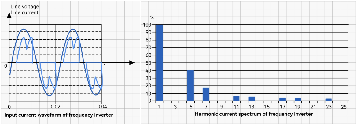
Frequency inverters convert a fixed frequency AC input into a variable frequency output to control motor speed. This process generates harmonics, which are multiples of the fundamental frequency. Harmonic interference can distort voltage and current waveforms, leading to reduced efficiency and potential damage to sensitive equipment.
1. Detection and Monitoring Tools:
Traditional tools like ammeters and voltmeters serve their purpose, but the integration of digital displays such as tachometers enhances the monitoring capability by converting analog quantities into digital values. This aids in identifying and quantifying harmonic frequencies.
2. Control Devices for Precise Management:
To ensure precise control in the face of harmonic interference, Analog-to-Digital (AD) modules and Programmable Logic Controllers (PLCs) come into play. These devices effectively convert analog quantities into digital feedback, allowing for nuanced control and mitigation strategies.
3. VFD Settings:
Fine-tuning the inverter settings proves crucial in mitigating harmonic interference. Users can choose output parameters like voltage or current signals, providing adaptability to specific operational needs. This flexibility is essential for tailoring the frequency converter’s output to meet diverse requirements.
Tackling Radio Frequency Conducted Emission Interference
Conducted emissions occur when high-frequency noise generated by the inverter propagates along power lines and other conductors. This type of interference can affect the operation of nearby equipment connected to the same power supply, causing malfunctions or even damage.
 1. Communication Protocols:
Leveraging advanced communication methods such as MODBUS, PROFIBUS, or PROFINET provides a comprehensive solution to radio frequency conducted emission interference. These protocols enable real-time data collection and control, minimizing interference’s impact on equipment sharing the same power grid.
2. Wiring Practices:
To minimize interference, meticulous wiring practices are essential. Ensuring a clear separation between power and signal lines and keeping them away from the inverter’s input and output lines minimizes the potential for interference, regardless of the distance between the equipment and the frequency converter.
Addressing Radio Frequency Radiation Interference
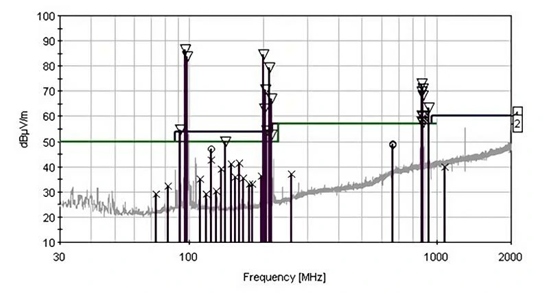
Radiated interference happens when the high-frequency signals generated by the frequency inverter are emitted into the surrounding environment as electromagnetic waves. These waves can interfere with the operation of nearby electronic devices, particularly those with sensitive radio frequency components.
 1. Effective Shielding Measures:
While frequency converters typically feature iron shells for shielding, additional measures are necessary for preventing radiation interference. Shielding the output lines with steel pipes fortifies the electromagnetic interference prevention, ensuring minimal impact on nearby electronic equipment.
2. Distance Considerations:
Maintaining a considerable distance between signal lines and main circuit lines, along with control lines, is pivotal. This separation minimizes cross-interference, creating a more controlled environment for electronic equipment operating in proximity to the frequency converter.
3. Grounding for Enhanced Shielding:
The effectiveness of shielding layers in preventing radiation interference hinges on reliable grounding. Ensuring the grounding of shielding layers enhances their capability to neutralize electromagnetic radiation, making the shielding measures more robust.
What Are the Main Steps to Solve On-Site Interference?
1. Adopting Software Anti-Interference Measures
Implementing software solutions such as adaptive filtering, error correction algorithms, and noise suppression techniques can significantly reduce the impact of interference. These measures can help in differentiating between actual signals and noise, improving the reliability of the system.
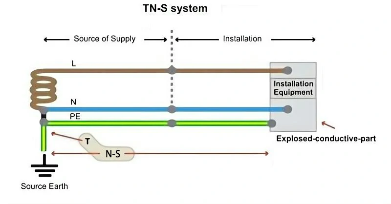
2.Perform Correct Grounding
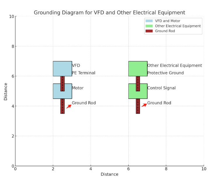
Proper grounding is essential to mitigate interference from frequency inverters. Ensure that all components are correctly grounded to provide a path for unwanted noise to dissipate safely. Grounding also helps to reduce potential differences that can cause interference.
- The main circuit terminal PE (E, G) of the inverter must be grounded.
- The grounding wire of the inverter should have a cross-sectional area of at least 4mm² and be kept within 20 meters in length.
- Other electrical equipment’s protective and operational grounding should have separate grounding poles and ultimately converge at the electrical grounding point of the distribution cabinet.
- Shielded grounds for control signals and main circuit wires should also have separate grounding poles and ultimately converge at the electrical grounding point of the distribution cabinet.
3.Block Interference Sources
Shielding the inverter and its components can prevent interference from spreading. Use metal enclosures and shielding materials to block electromagnetic waves from escaping and affecting other devices. Properly shielded cables and components can also minimize conducted and radiated emissions.
4.Reasonable Wiring
Organize wiring layouts to minimize the risk of interference. Keep power and signal cables separate, and avoid running them parallel to each other. Use twisted pair cables for signal lines to reduce the impact of electromagnetic fields. Proper wiring practices can significantly reduce both conducted and radiated interference.
5.Isolation of Interference
Using isolation transformers or optocouplers can help in breaking the path of interference. These devices ensure that signals can be transmitted without direct electrical connection, reducing the potential for noise to propagate.
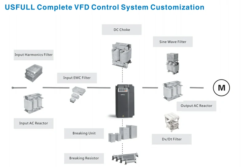
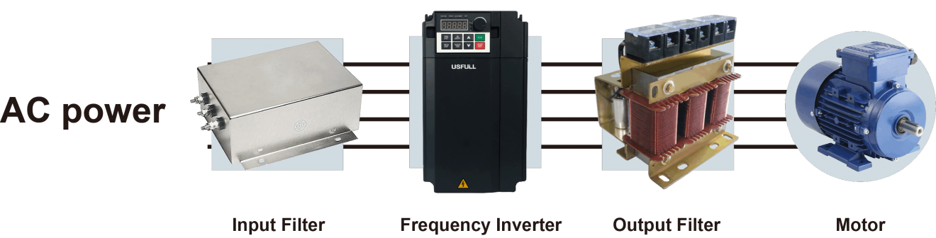
6. Set Filters in the System Circuit
Filters are used to suppress interference signals conducted through power lines:
- Input Filters: Reduce conducted interference from the power supply. They include line filters (composed of inductors to increase impedance at high frequencies) and radiation filters (composed of high-frequency capacitors to absorb high-frequency harmonic components).
- Output Filters: Reduce high-order harmonic components in the output current. They also mitigate additional torque caused by harmonic currents in motors.
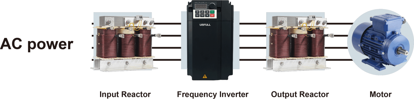
7.Using Reactors
Reactors, or inductors, can be added to the input and output of frequency inverters to limit the rate of voltage change and reduce harmonic distortion. Reactors help in smoothing the current waveform, thus minimizing harmonic interference and improving the overall power quality.
Conclusion
Managing interference from frequency inverters is essential for maintaining the performance and reliability of industrial systems. By implementing appropriate measures such as software adjustments, proper grounding, shielding, reasonable wiring, isolation, filtering, and using reactors, the impact of electromagnetic interference can be significantly reduced, ensuring the smooth operation of frequency inverters and nearby electronic equipment.