Introduction
In modern industrial applications, the precise control of motor speed and torque is crucial for efficiency and productivity. The use of frequency inverters, also known as variable frequency drives (VFD) or variable speed drives, has become widespread for this purpose. One important consideration when implementing a frequency inverter system is the distance between the frequency inverter and the motor. This article will explore the factors that determine the allowable cable length between these two components and its implications for various industrial settings.
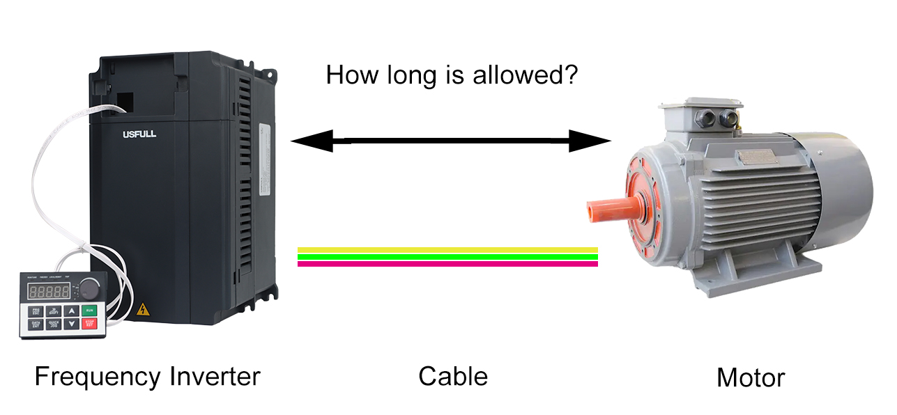
Definition of Distance Between Frequency Inverter and Motor
The distance between the frequency inverter and the motor refers to the length of the cable that connects these two devices. This distance can significantly affect the performance and reliability of the motor control system.The distance between the frequency inverter and the motor can be classified into three categories:
- Short Distance:Distance ≤ 20m
- Medium Distance:Distance > 20m and ≤ 100m
- Long Distance:Distance > 100m
Industrial Use Site Occasions
1. Short Distance
For short distances (≤ 20m), the frequency inverter and the motor can be directly connected without additional considerations. This straightforward setup minimizes potential issues caused by harmonics and EMI, ensuring stable operation.
2. Medium Distance
For medium distances (> 20m and ≤ 100m), the frequency inverter and the motor can still be directly connected. However, it is necessary to adjust the carrier frequency of the inverter to reduce harmonics and interference. Proper tuning of the carrier frequency helps maintain system stability and performance over these extended distances.
3. Long Distance
For long distances (> 100m), direct connection between the frequency inverter and the motor requires additional measures. Besides adjusting the inverter’s carrier frequency, it is essential to install output AC reactors. These reactors help mitigate the effects of long cable runs by smoothing voltage spikes and reducing harmonic distortion, protecting the motor from potential damage.
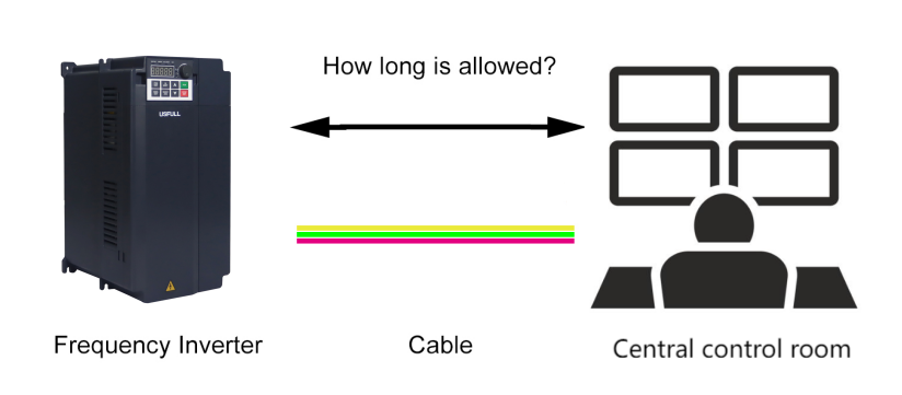
Selection Situation in Highly Automated Factories
Highly automated factories, such as those found in the automotive, semiconductor, and electronics industries, rely heavily on precise motor control and rapid response times. In such environments, the cable length between the frequency inverter and the motor must be carefully managed to ensure optimal performance.
1. Short Distance
If the frequency inverter is installed within the central control room, the control console and the inverter can be directly connected using 0-5V or 0-10V voltage signals and some switching signals. However, the high-frequency switching signals of the inverter can cause electromagnetic interference with low-power control signals. Thus, it might be preferable not to place the inverter directly within the control room to avoid clutter and potential interference.
2. Medium Distance
For medium distances between the frequency inverter and the central control room, a 4-20mA current signal and some switching signals can be used for control connections. If the distance is even greater, RS485 serial communication can be employed for reliable connectivity.
3. Long Distance
When the distance between the frequency inverter and the central control room exceeds 100m, communication intermediate relays can extend the reach up to 1km. For distances beyond this range, fiber optic connectors are necessary, enabling connections up to 23km. These methods ensure robust and interference-free signal transmission over long distances.
The Following Factors Are Particularly Important to Ensure Optimal Performance:
1. Cable Quality and Specifications
Selecting high-quality cables with appropriate specifications, such as low capacitance and adequate shielding, helps reduce signal degradation and electromagnetic interference. This is especially important in highly automated settings where numerous VFD and motors operate in close proximity.
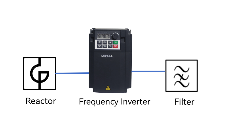
2. Use of Output Reactors and Filters
Output reactors and filters can be employed to mitigate the effects of long cable runs. These devices help to smooth out voltage spikes, reduce harmonic distortion, and protect the motor from potential damage caused by reflected waves.
3. Compliance with Manufacturer Guidelines
Manufacturers of frequency inverters and motors typically provide guidelines on the maximum allowable cable length for their equipment. Adhering to these recommendations ensures that the system operates within safe and efficient parameters, minimizing the risk of faults and downtime.
4. Implementation of Advanced Control Strategies
In highly automated factories, advanced control strategies such as field-oriented control (FOC) or direct torque control (DTC) can be utilized to enhance motor performance over longer cable distances. These techniques offer improved precision and responsiveness, compensating for potential signal delays and losses.
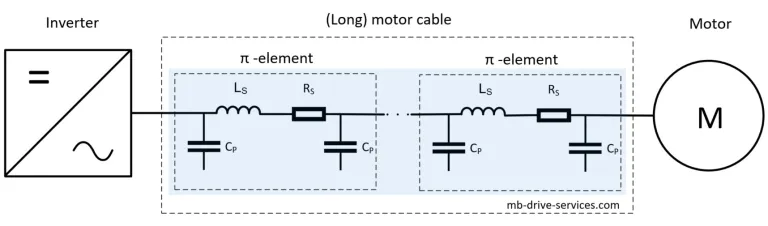
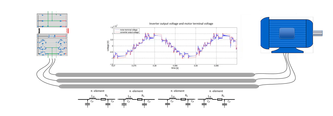
Cable modeling using pi-elements
Conclusion
The allowable cable length between a frequency inverter and a motor is a critical factor in the design and implementation of motor control systems. By understanding the variables that influence this distance and selecting appropriate cables and protective measures, industrial operations can achieve reliable and efficient performance. In highly automated factories, where precision and responsiveness are paramount, careful planning and adherence to best practices are essential to maintaining optimal system functionality.