Introduction
Central air conditioning systems are a cornerstone of modern building management, providing comfort and climate control across various commercial and residential spaces. The integration of a frequency inverter, also known as a variable frequency drive (VFD), has revolutionized how these systems operate. By optimizing the energy consumption and enhancing system performance, variable frequency inverters or variable speed drives play a critical role in improving the efficiency of central air conditioning systems.
Working Principle and Structure of Central Air Conditioning System
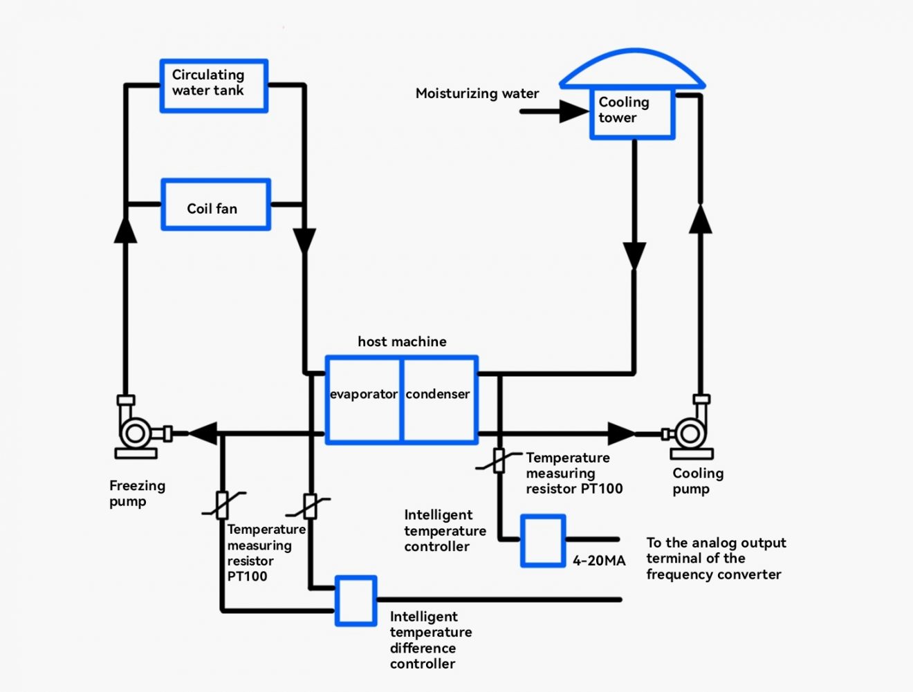
Central air conditioning systems are primarily composed of three main parts: the main unit, the chilled water circulation system, and the cooling water circulation system. Depending on the load type, central air conditioning systems can be classified into two major categories:
Constant Torque Loads: Examples include screw or centrifugal refrigeration compressors that require a minimum torque output and exhibit a nearly linear relationship between speed and power.
Variable Torque Loads: Examples include cooling water circulation systems, refrigerant circulation water systems (heat pump circulation water systems), cooling tower fan systems, and coil fan systems. These fan and pump loads have a cubic relationship between shaft power and speed, allowing for significant energy savings.
Energy Saving Principle of Refrigeration Compressors
For instance, in a vapor compression refrigeration cycle, the cooling process can be regulated using variable frequency control to adjust the screw compressor’s speed. The power output of a screw compressor can be continuously adjusted from 10% to 100%. Data shows that when the screw compressor load exceeds 50%, its power is linearly proportional to the load, but below 40%, the actual power consumption exceeds theoretical calculations. Consequently, variable frequency technology cannot achieve optimal energy savings across the entire load range, limiting its application for compressor energy-saving retrofits.
Energy Saving Principle of Fans and Pumps
According to fluid mechanics, the output flow rate (Q) of centrifugal fluid transmission equipment (e.g., centrifugal pumps and fans) is directly proportional to its speed (n); the output pressure (P) or head is proportional to the square of its speed; and the output power (N) is proportional to the cube of its speed.
Due to the unique characteristics of central air conditioning systems, two factors must be considered: the rated flow and head specifications of the pump itself and the deviation between the actual supply temperature differential or pressure requirements and the unit’s standard specifications. For instance, using real-time temperature data collection and smart temperature controllers to control the frequency inverter’s adjustments can optimize the chilled pump system’s operation while preventing phenomena such as “dead pump” or “flow interruption.”
Actual Equipment Conditions
- Closed-Loop Control of Chilled Water Pump System (Monitoring Inlet and Outlet Water Temperature Difference)
Central air conditioning systems have a standard chilled water temperature of 12°C at the inlet and 7°C at the outlet, with an allowable temperature difference of 5°C for the condenser. If the actual temperature difference is 2°C, the actual demand for chilled water is only 40% of the supply capacity. Under variable frequency conditions, the pump speed only needs to operate at 40% of the rated speed, reducing energy consumption to less than 10% of the rated energy. Therefore, there’s significant potential for energy savings.
To ensure sufficient chilled water flow to the farthest terminal equipment, the minimum operating frequency of the chilled pump inverter should be set (usually 25 Hz), locking the pump’s minimum speed. An intelligent temperature controller monitors the chilled water temperature difference to control the inverter frequency, increasing it as needed when the return water temperature exceeds the set value.
- Closed-Loop Control of Chilled Water Pump System in Heating Mode (Monitoring Inlet and Outlet Water Temperature Difference)
This mode is similar to the cooling mode and is applicable during heating operations (autumn and winter).
- Open-Loop Control of Cooling Water Circulation Pump (Monitoring Inlet and Outlet Water Temperature Difference)
The standard temperature difference for cooling water circulation in central air conditioning systems is 4°C to 8°C, and for cooling towers, it is 3°C to 5°C. The system consists of cooling pumps, cooling towers, and condensers. The cooling water circulation system is influenced by both outdoor environmental temperatures and indoor heat loads. Thus, installing a temperature difference sensor between the supply and return main pipes is a rational energy-saving approach.
Under stable outdoor conditions, a large temperature difference indicates a high indoor heat load, necessitating an increase in cooling pump speed to enhance circulation. Conversely, a smaller temperature difference allows for a reduction in pump speed. This approach can save 5-10% more energy than measuring return water temperature alone.
Therefore, when assessing actual operating conditions, relying solely on motor current may lead to erroneous conclusions about energy-saving potential. It is crucial to consider actual operational data, such as system capacity selection, seasonal changes, and load variations. Most systems deviate from standard specifications, often experiencing small temperature differences, excessive head, and excessive flow. Utilizing variable frequency technology can save excess flow and head, enabling the system to operate efficiently, meeting system requirements while minimizing energy consumption.
- Control of Coil Fan Systems
Each room is equipped with a coil fan unit (0.40 kW, 220V) with a maximum air temperature difference of 10°C to 15°C (generally 8°C). The coil fan system uses water and air to transfer indoor load heat, with the majority of the cooling or heating load handled by the coil’s refrigerant or heat medium water. Fans mainly meet ventilation needs to enhance room comfort and manage some heating or cooling loads.
Originally, fan operation was manually controlled with a three-speed switch, but variable frequency control has been implemented. After modification, room temperatures, especially in winter, are stable at 17°C ± 1°C, saving an average of 80% in energy consumption compared to fixed frequency operation, equating to over 60% of rated power. Additionally, noise levels are significantly improved.
- Cooling Tower Fan Control
Cooling tower systems typically have two fans and operate with full-speed direct start control. Both fans run at full speed, lacking effective cooling effect detection and missing opportunities to save energy under natural cooling conditions. In particular, during spring, autumn, and winter, manual control cannot promptly respond to cooling tower outlet temperature changes, causing energy waste.
During the retrofit, fans are set to start at 35°C and stop at 30°C, with the 35°C to 30°C range used for frequency adjustment based on temperature PID variable volume control. Test results show that energy consumption with variable volume control is approximately 40% of fixed frequency operation, avoiding the waste associated with manual start-stop control. According to data from successful central air conditioning retrofits, cooling tower systems achieve energy savings of over 40%, with some systems with large capacity cooling tower tanks saving over 50%.
Features of Frequency Conversion Energy Saving System
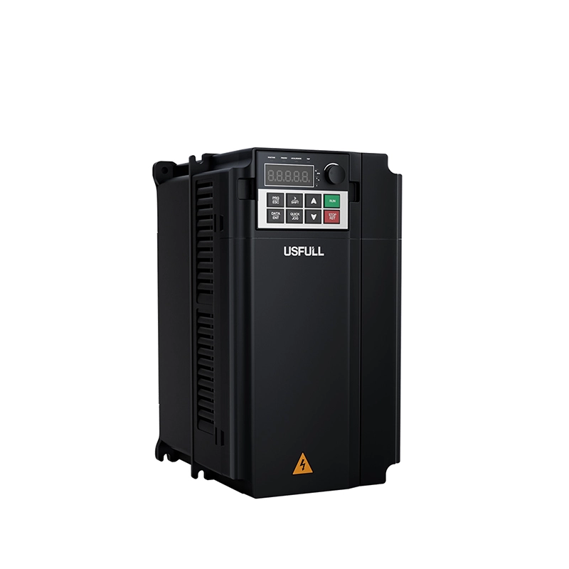
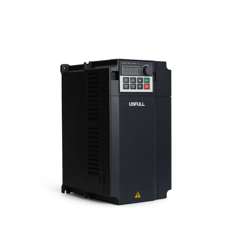
The frequency inverter interface features LED displays with comprehensive monitoring parameters and a simple, user-friendly layout.
Temperature/differential sensors have digital dual-screen LED displays, making temperature parameter settings easy and straightforward to monitor.
Frequency inverters are equipped with electronic protections for overcurrent, overload, overvoltage, and overheating, along with extensive fault alarms, effectively safeguarding the water supply system.
Installing frequency inverters enables motors to perform soft starts and stepless speed adjustments, significantly reducing mechanical wear on pumps and motors, extending the life of the pipe system.
The system achieves PID closed-loop temperature control, ensuring smooth indoor temperature changes and greatly enhancing comfort.
Conclusion
The incorporation of a frequency inverter, or variable frequency drive (VFD), within central air conditioning systems marks a significant advancement in HVAC technology. By tailoring motor speeds to meet fluctuating demand, these systems enhance energy efficiency, reduce operational costs, and extend equipment life. As technology continues to evolve, the role of variable speed drives in HVAC systems is poised to become even more integral to achieving sustainable and efficient climate control solutions.

