The frequency converter protects the motor, but it does not mean that the motor will not burn out. In most cases, the frequency converter can protect the motor from burning out, such as overload, lack of phase, etc., but this depends on your parameter settings and actual use. For example, your overcurrent protection setting is too large (generally the default is 150 %), if you turn it up, the motor will easily burn if it runs above 100% rated current for a long time. Another example, involves frequent starts and stops coupled with high currents. In this scenario, if the overload is simply reset and the motor is restarted without addressing the underlying issues, there is a high risk of motor burnout.
If you want the inverter to completely protect the motor, you need to be careful with how you use it. Make sure to set the parameters correctly and not just increase the overload too much. Also, regularly check and take care of the motor. Keep an eye on how much load is on it; we suggest keeping the current below 90%. If it goes above that, control it and check it carefully.
1.Why Does the Inverter Lead to Motor Burnout?
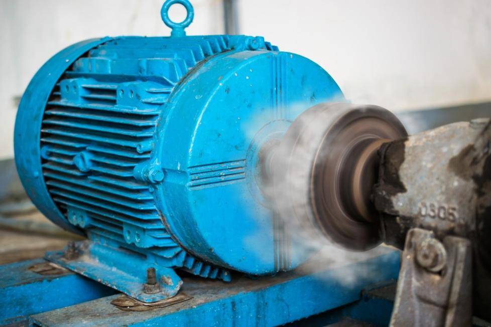
The heat dissipation of ordinary asynchronous motors relies on the fan behind the motor to dissipate heat. When the motor operates at a low frequency for an extended period, meaning it runs below its rated frequency, the motor speed decreases, resulting in reduced air blown by the fan. This leads to inadequate heat dissipation, causing the motor to become excessively hot. If there’s an issue with the motor, the motor current will rise. If this surpasses the inverter’s maximum current, the inverter activates protection measures, halting the output and report a fault code to inform the user.
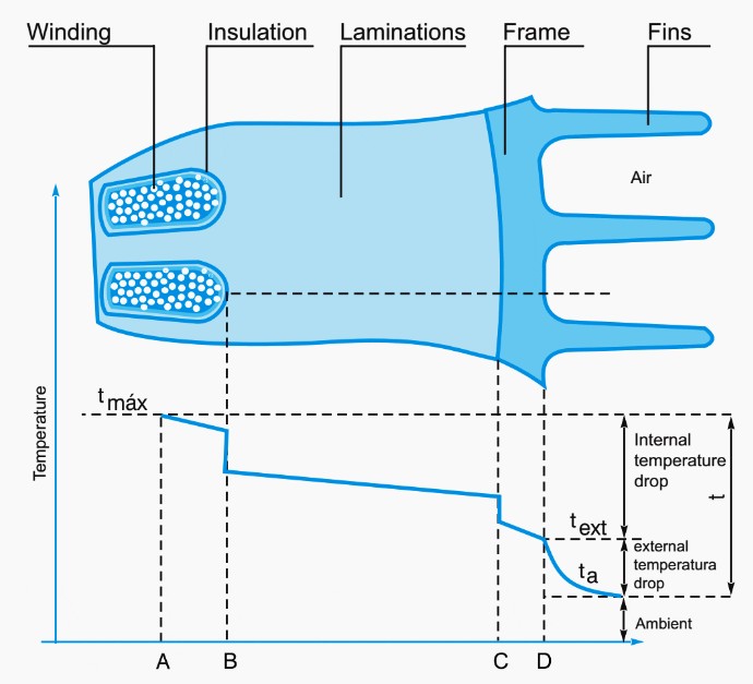
When the inverter displays OC, it means overcurrent. The solution is to replace the motor with a special variable frequency motor, or add a cooling fan to the motor. Or replace it with a more powerful motor.
2.Interpretation of burn-in technology
“Inverters that burn motors are basically short-circuited between turns, between phases and to ground. Why are inverters so easy to burn motors, and most of them are variable-frequency motors? What technical indicators does it have to do with it?”
In the scenario of an industrial frequency power supply, the motor winding receives a three-phase 50Hz sine wave voltage. The induced voltage generated by the winding remains low, and there is minimal surge component in the line.
In the case of variable frequency power supply, the inverter part converts the DC voltage into a three-phase AC voltage, and realizes the output of the three-phase AC voltage by controlling the switching elements of the six bridge arms to turn on and off Upon connection to the frequency converter, the carrier frequency reaches several thousand to over ten kilohertz. This high frequency subjects the motor stator winding to a rapid increase in voltage, akin to applying a steep impulse voltage to the motor, challenging the insulation between them. The increase voltage change rate (dv/dt) leads to uneven voltage distribution among the winding turns, creating unfavorable power supply conditions for the motor. This, in turn, increases the likelihood of faults like short circuits between winding turns, escalating the motor failure rate.
The PWM waveform output by the frequency converter also produce various harmonic voltage components in the motor winding power supply circuit. It can be seen from the inductor characteristics that the faster the change speed of the current flowing through the inductor, the higher the induced voltage of the inductor.
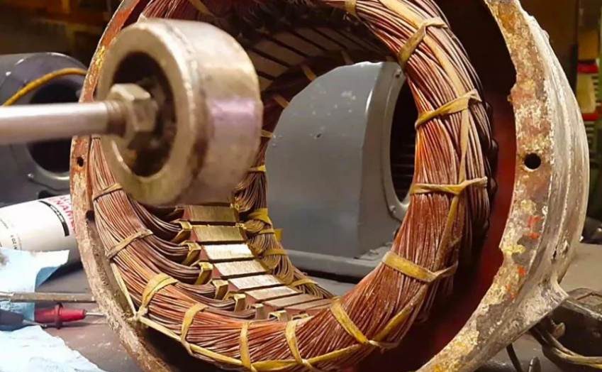
The induced voltage of the motor winding is higher than that of the power supply at power frequency. Insulation defects that are not exposed during industrial frequency power supply cannot withstand the impact of voltage induced by high-frequency carriers, so voltage breakdown occurs between winding turns or between phases. Despite the presence of a comprehensive protection circuit in the frequency converter, it does not render the motor completely immune to burning. In fact, the protection circuit of the frequency converter is not all-powerful. In comparison to industrial frequency power supply, the utilization of an inverter increases the likelihood of motor burnout. The phase-to-phase, inter-turn short circuit or grounding of the motor winding causes a sudden short circuit of the motor winding, which may cause the module to explode or the motor to burn out during operation.
The frequency converter’s semiconductor switch rapid switching induces pulse overvoltage on motor terminals, peaking around twice the DC voltage. This poses harm to the motor, especially endangering ground insulation. Repeated exposure accelerates ground insulation aging due to high-voltage impacts.
3.Causes of motor burnout caused by frequency inverter
In fact, motor failures are not caused by the motor itself. Most of them are caused by irregular debugging of the frequency converter or the use of a non-variable frequency motor as a variable frequency motor. The main situations include the following:
1.Use ordinary motors as variable frequency motors.
The cooling fan of an ordinary motor is connected to the rotating shaft, faces instability and fails to attain the motor’s rated speed when a frequency converter adjusts the speed. The cooling fan cannot function normally, causing poor heat dissipation of the motor; in addition, ordinary motors are not designed according to frequency conversion requirements, causing the motor to heat up or burn out.
2.The variable frequency motor and the frequency converter can be directly connected together for use without debugging.
The two most commonly used methods for inverter control of motors are vector control and V/F curve control. To implement either method, initial determinations must be made, including the motor type (synchronous or asynchronous, with or without an encoder), rated power, voltage, current, speed or number of poles, rated frequency, maximum operating frequency, acceleration and deceleration times for motor start and stop, as well as the chosen protection method, protection proportional coefficient, and carrier frequency. Once these parameters are set, the selection between vector control and V/F control is made. For vector control, the motor needs to undergo either no-load dynamic self-learning or static self-learning with a load for accuracy. In contrast, V/F control does not require self-learning; after adjusting the parameters, the system can be powered on and run directly.
3.The variable frequency motor fan’s operational direction does not align with the indicated rotation direction on the fan. Consequently, the fan fails to operate, leading to compromised heat dissipation for the motor. The inability to dissipate the generated heat results in motor overheating and potential burnout.
4.Of the above three situations, items 2 and 3 occur most frequently.
In response to the above situation, it is recommended that customers choose a variable frequency motor when choosing an inverter to control a motor. The inverter should be chosen from a manufacturer with good quality, despite a slightly higher initial cost, ensures quality and prolonged trouble-free operation. This minimizes the risk of problems stemming from motor issues or production halts due to inverter failures. Additionally, reliable after-sales service is guaranteed with prompt response times for high-quality inverters.