Faulty IGBT modules can silently damage VFD systems—causing machine shutdowns, missed delivery timelines, and mounting repair costs. Static measurement is your first defense.
Static measurement of VFD IGBT modules helps identify early-stage faults, prevent costly downtime, and extend the lifespan of entraînement à fréquence variable systems.
Want reliable VFD performance? First, understand its core component: the IGBT module.

What Is the Structure of a VFD IGBT Module?
A VFD (Variable Frequency Drive) IGBT (Insulated Gate Bipolar Transistor) module is a hybrid semiconductor component combining the fast switching capabilities of a MOSFET with the high current-handling capacity of a BJT. In VFD applications, it is responsible for the high-efficiency conversion of DC to AC.
Structurally, a VFD IGBT module typically contains multiple power units integrated into one block. For example, a seven-unit IGBT module, includes three rectifier units, three inverter units, and one braking unit. The terminals are usually labeled G (Gate), C (Collector), and E (Emitter). Internally, each transistor also includes a flyback (or freewheeling) diode that ensures smooth current transition during switching operations.
This integrated module design ensures high reliability, ease of installation, and efficient thermal management, making it ideal for variable speed drive (VSD) systems and variable frequency inverters used across industries.
VFD IGBT Module Principle Circuit Analysis
The basic function of an IGBT module within a variable frequency drive is to switch high voltages and currents efficiently, converting DC input into adjustable-frequency AC output.
Each IGBT in the module operates by applying voltage between the gate and emitter. When positive voltage is applied, a conductive channel forms, allowing current to pass between collector and emitter. When this voltage is removed, the channel collapses, and the IGBT turns off.
The principle circuit includes:
Rectifier Circuit: Converts AC input to DC.
DC Link: Includes smoothing capacitors and sometimes a braking circuit.
Inverter Circuit: Made up of IGBT switches arranged in a bridge to convert DC to AC.
In module, the internal arrangement supports coordinated switching using PWM signals, offering precise motor speed and torque control in VFD systems. Its efficient design allows it to support heavy industrial loads while maintaining system stability.
VFD IGBT Module Common Fault Handling
VFD IGBT modules are subjected to high electrical and thermal stress, making them prone to failure if not properly managed. Common fault types include overcurrent, overheating, and short circuits—often caused by poor cooling, contamination, or incorrect wiring.
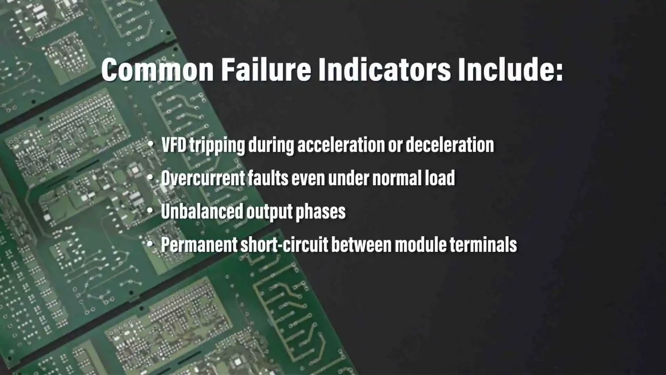
Common failure indicators include:
VFD tripping during acceleration or deceleration
Overcurrent faults even under normal load
Unbalanced output phases
Permanent short-circuit between module terminals
For example, overcurrent trips during acceleration might suggest a failure in the lower IGBT bridge, while during deceleration it might be an upper bridge fault. In such cases, measurement of the U, V, W outputs against the P and N terminals can help confirm whether the fault lies in the module or its driver circuit.
Regular inspection of cooling fans, proper grounding, and shielding against electromagnetic interference are essential practices in fault prevention for variable frequency inverter systems.
Entraînement à fréquence variable IGBT Module Detection Method
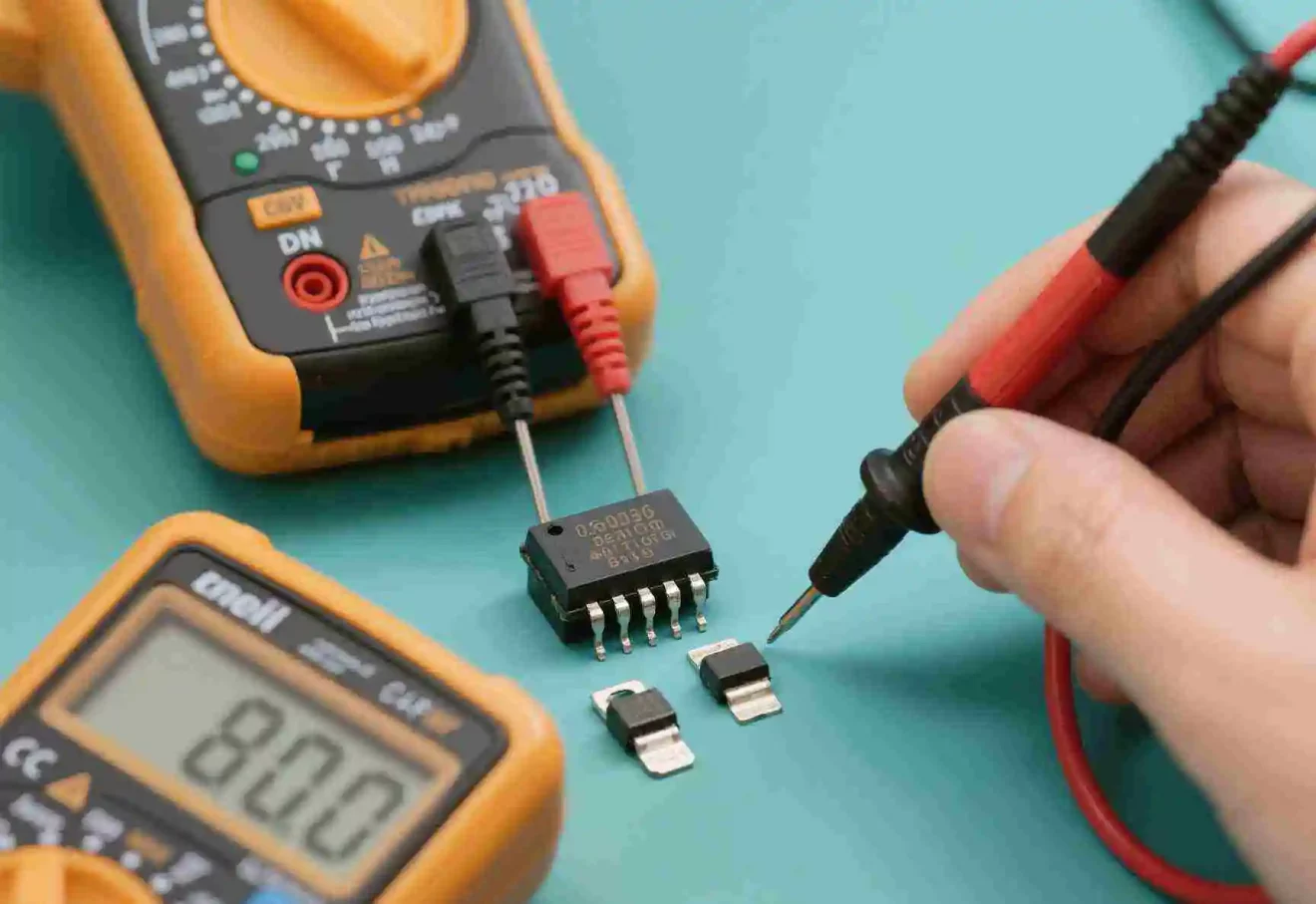
Diagnosing a suspected faulty IGBT module involves both polarity identification and functionality testing using a digital or analog multimeter.
Polarity identification:
Set the multimeter to R×1kΩ.
Identify the Gate (G) terminal: When measuring between one terminal and the other two, if both measurements show infinite resistance regardless of probe polarity, that terminal is the Gate.
Between the remaining two, if switching probe positions changes the resistance significantly, the one connected to the black probe (lower resistance) is the Emitter (E), and the red probe is on the Collector (C).
Functionality check:
Set the meter to R×10kΩ.
Connect black to Collector and red to Emitter—the meter should read zero.
Briefly touch Gate and Collector together with a finger; the module should conduct, and the meter will show resistance.
Then touch Gate and Emitter together to turn it off; the resistance returns to zero.
If the IGBT does not respond as above, it may be damaged. Always ensure the test is performed with proper safety measures, and only when the system is de-energized.
Static Measurements of VFD IGBT Modules
Static measurements are essential for non-invasive, offline diagnostics of entraînement à fréquence variable IGBT modules. Using the diode test mode on a multimeter, technicians can measure voltage drops across internal diodes and transistor junctions to evaluate module health.
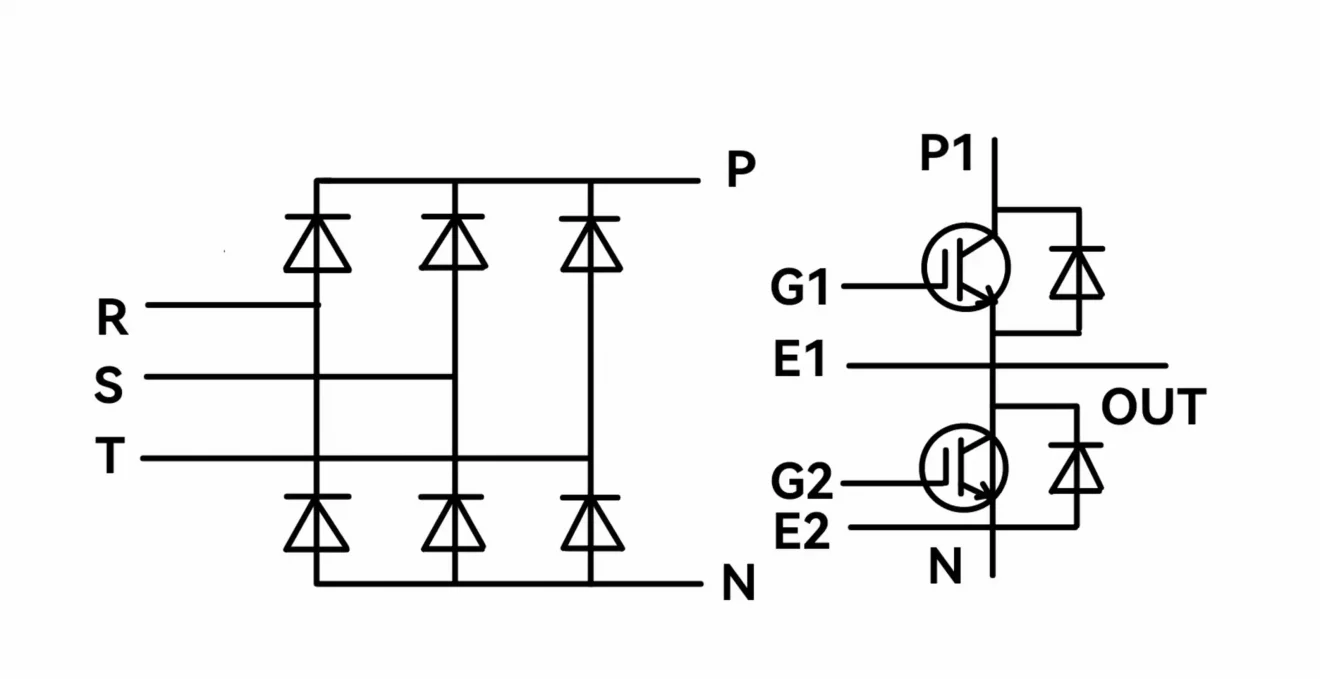
Three-phase bridge rectifier and IGBT electrical schematics
Here’s a quick method for testing the seven-unit module:
Place one probe on the P (DC+) terminal and use the other probe to measure terminals R, S, T (rectifier), PB (brake), and U, V, W (inverter) one by one.
Reverse the probes and repeat.
Reference your readings against known values or the module’s datasheet. Values should fall within a predictable range (typically around 0.4–0.6V for diode junctions).
Measurements significantly deviating from expected values may indicate shorted IGBT junctions or open circuits. Static testing helps isolate which of the rectifier, inverter, or brake units may be damaged—without energizing the variable frequency inverter.
Seven-unit IGBT Measurement Reference
| Measuring Point | Measurement Results | |||||
| R(S,T) | PB | U(V,W) | P | N | ||
| Multimeter Pen (+ for red pen, – for black pen) |
+ | – | 0.55V±0.05V | |||
| – | + | 0.55V±0.05V | ||||
| + | + | – | 0.4V±0.05V | |||
| – | + | 0.4V±0.05V | ||||
| – | + | 0.7V±0.05V | ||||
| – | + | ↑V | ||||
| – | – | – | + | – | ↑V | |
| + | + | + | + | – | ↑V | |
Additionally, modules with built-in thermal sensors can also be checked for correct resistance values across temperature-sensing terminals, ensuring overheat protection is functional.
Static testing keeps your variable frequency drive system healthy and your downtime minimal.