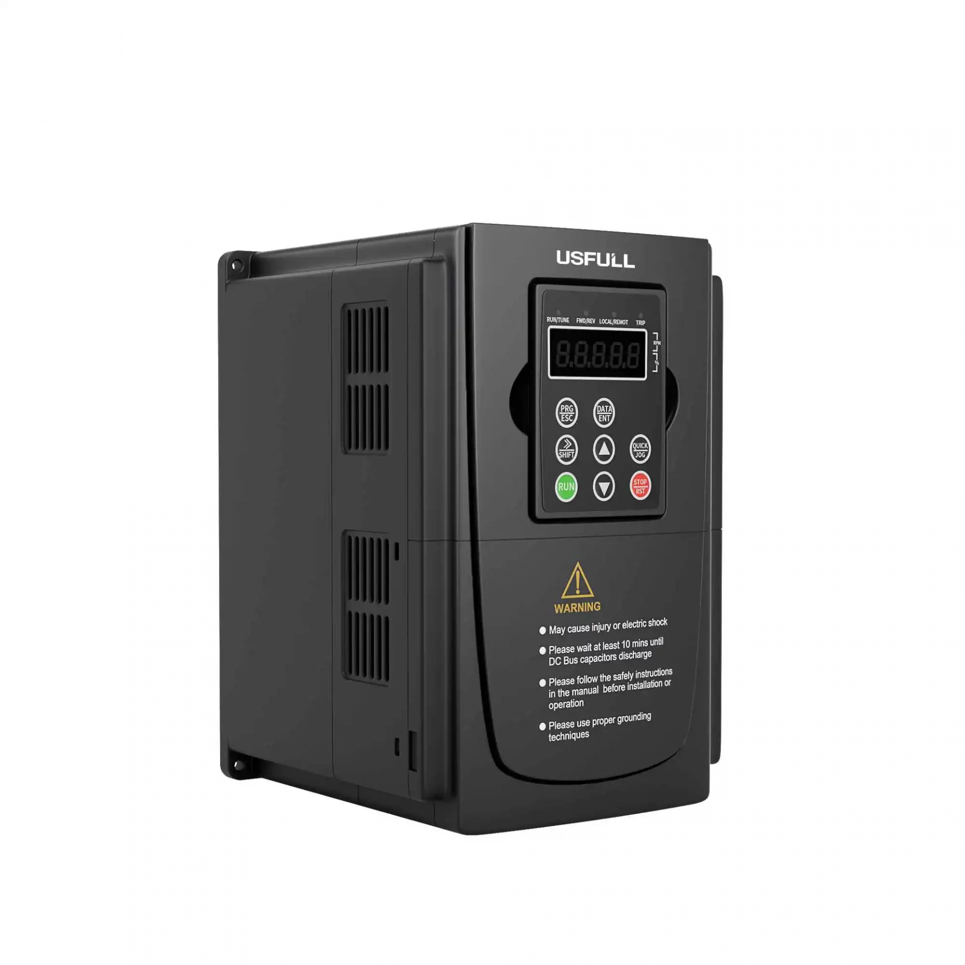
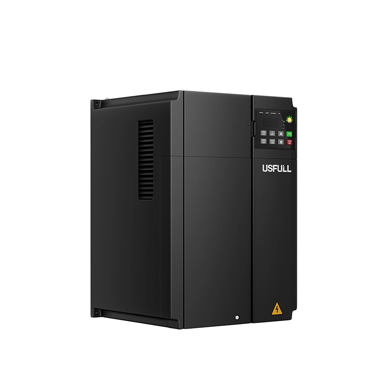
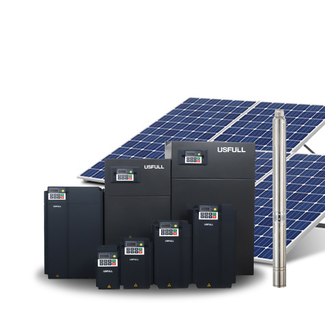
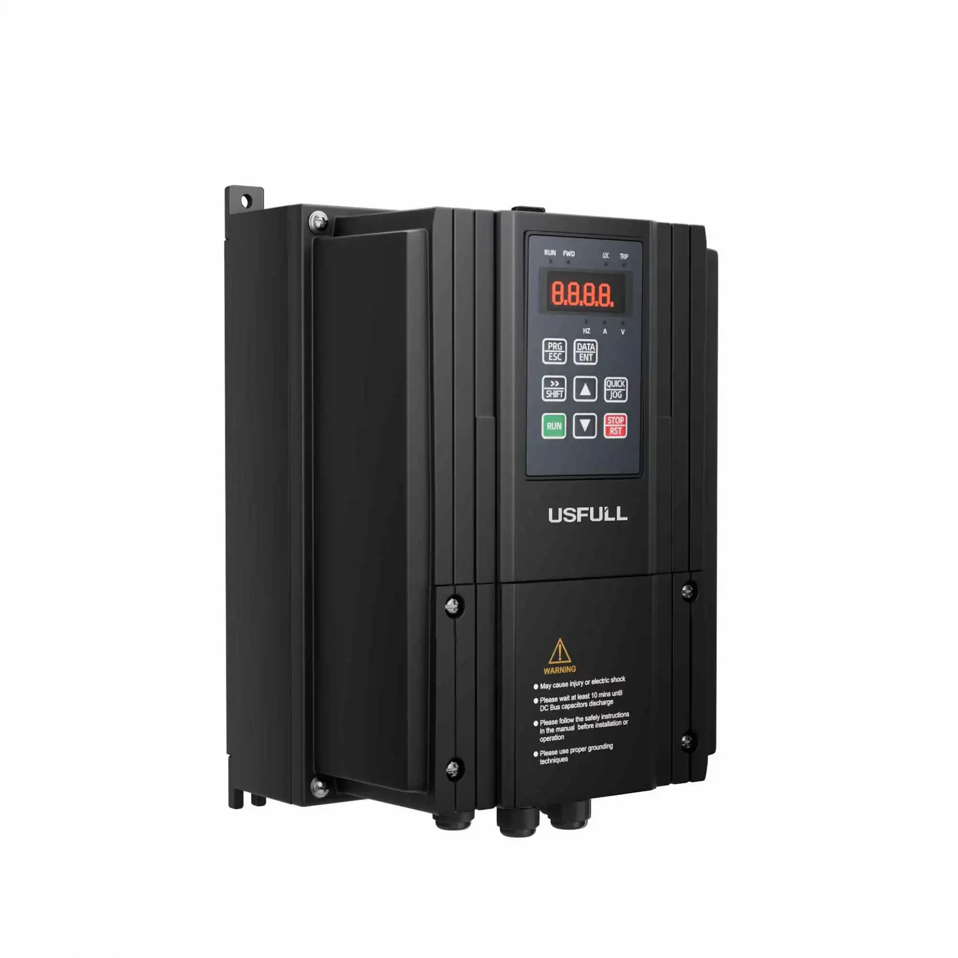
L'utilisation d'un convertisseur de fréquence ou entraînement à fréquence variable (VFD) pour contrôler simultanément plusieurs moteurs est une pratique courante dans diverses applications industrielles. Dans ce cas, tous les moteurs sont commandés par la même fréquence de sortie de l'appareil. variateur de vitessece qui garantit théoriquement des vitesses synchronisées. Cependant, en raison des différences de fabrication des moteurs et des conditions de charge, des divergences dans les vitesses réelles des moteurs peuvent se produire. Ces différences, si elles ne sont pas prises en compte, peuvent entraîner des erreurs cumulatives. Vous trouverez ci-dessous six considérations essentielles à prendre en compte lors de l'utilisation d'un convertisseur à fréquence variable pour piloter plusieurs moteurs.
Note 1 : La différence de puissance du moteur ne doit pas être trop importante.
Lors de l'utilisation d'un onduleur VFD pour entraîner plusieurs moteurs, les puissances nominales des moteurs doivent être aussi proches que possible, idéalement à deux niveaux de puissance l'un de l'autre. Des différences de puissance importantes peuvent entraîner une répartition inégale de la charge, les moteurs ayant une puissance nominale plus élevée supportant une charge plus importante, ce qui provoque un déséquilibre. Ce déséquilibre peut affecter l'efficacité globale du système et entraîner une usure accrue des moteurs. Pour minimiser ce risque, il convient de sélectionner des moteurs de puissance nominale similaire et d'envisager d'augmenter le niveau de puissance du moteur d'un degré pour garantir un fonctionnement fiable.
Note 2 : Il est préférable que les moteurs soient fabriqués par le même fabricant.
Pour des performances et une synchronisation optimales, il est conseillé d'utiliser des moteurs du même fabricant, de préférence du même lot de production si possible. Les moteurs produits par des fabricants différents, voire par des lots différents, peuvent présenter des caractéristiques variables, telles que le glissement (différence entre la vitesse du champ magnétique tournant du stator et celle du rotor). L'utilisation de moteurs aux caractéristiques homogènes permet de maintenir la synchronisation et de réduire la probabilité d'erreurs cumulatives, ce qui garantit une répartition plus uniforme de la charge et un fonctionnement plus souple.
Note 3 : Tenir compte de la longueur du câble du moteur
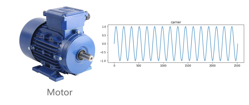
La longueur des câbles du moteur a un impact significatif sur les performances de l'appareil. entraînement à fréquence variable. Des câbles plus longs augmentent la capacité entre les câbles eux-mêmes et la terre, ce qui peut introduire des courants capacitifs à haute fréquence en raison du contenu harmonique élevé de la tension de sortie du variateur. Ces courants peuvent perturber le fonctionnement de l'appareil et en dégrader les performances. Il est donc essentiel de tenir compte de la longueur totale des câbles lors de la planification de l'installation. Veillez à ce que la longueur combinée de tous les câbles connectés à l'EFV soit conforme aux limites recommandées par le fabricant. Si nécessaire, installez des réactances ou des filtres à la sortie du variateur pour atténuer les effets des longs câbles.
Note 4 : Le variateur de fréquence ne peut fonctionner qu'en mode de contrôle V/F.
Lors de la commande de plusieurs moteurs avec un seul convertisseur à fréquence variableIl est donc essentiel d'utiliser le mode de contrôle V/F (tension/fréquence) plutôt que le contrôle vectoriel. Le mode de contrôle V/F est mieux adapté aux applications multi-moteurs car il maintient un rapport tension/fréquence constant entre tous les moteurs, ce qui garantit un contrôle plus uniforme de la vitesse. En outre, le courant nominal de fonctionnement du variateur doit être au moins 1,2 fois supérieur au courant nominal total de tous les moteurs combinés. Cela garantit que l'EFV peut supporter la charge sans être surchargé, ce qui contribue à la longévité de l'EFV et des moteurs.
Note 5 : Afin de protéger le moteur, un relais thermique doit être installé devant chaque moteur.
Pour protéger chaque moteur de la surchauffe et des dommages potentiels, un relais thermique doit être installé devant chaque moteur. Contrairement aux disjoncteurs à air, les relais thermiques offrent une protection plus précise contre les surcharges en détectant le flux de courant excessif dû à la surchauffe et en déconnectant le moteur de l'EFV avant que tout dommage ne se produise. Cette configuration empêche le circuit principal d'être interrompu pendant le fonctionnement de l'EFV, assurant une protection continue pour chaque moteur et sauvegardant l'intégrité de l'ensemble du système.

Note 6 : L'unité de freinage et la résistance de freinage doivent être ajoutées.
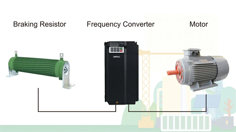
Pour les applications nécessitant une décélération rapide, il est essentiel d'ajouter une unité de freinage et une résistance de freinage à l'unité de freinage. onduleur VFD. Ces composants empêchent les surtensions pendant le freinage en dissipant l'énergie excédentaire générée lorsque les moteurs ralentissent. Dans certains cas, les petits variateurs de vitesse peuvent être équipés d'une unité de freinage intégrée, auquel cas seule une résistance de freinage externe doit être connectée. En incluant ces composants, vous garantissez un fonctionnement plus souple et plus sûr lors d'une décélération rapide, évitant ainsi tout dommage potentiel à l'EFV et aux moteurs.
En abordant ces six questions clés, vous pouvez optimiser les performances et la fiabilité de votre système d'information. entraînement à fréquence variable lorsque vous pilotez plusieurs moteurs. Chaque point met en évidence des aspects critiques de la conception du système, ce qui permet d'éviter les pièges les plus courants et de garantir que vos moteurs fonctionnent de manière efficace et harmonieuse.

