Introducción
Los sistemas centrales de aire acondicionado son la piedra angular de la gestión moderna de edificios, ya que proporcionan confort y control climático en diversos espacios comerciales y residenciales. La integración de un convertidor de frecuenciatambién conocido como variador de frecuencia (VFD)ha revolucionado el funcionamiento de estos sistemas. Optimizando el consumo de energía y mejorando el rendimiento del sistema, convertidores de frecuencia variable o variadores de velocidad desempeñan un papel fundamental en la mejora de la eficiencia de los sistemas centrales de aire acondicionado.
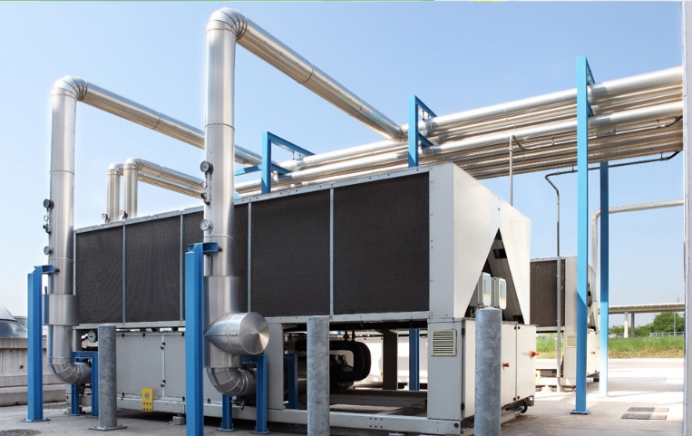
Principio de funcionamiento y estructura del sistema central de aire acondicionado
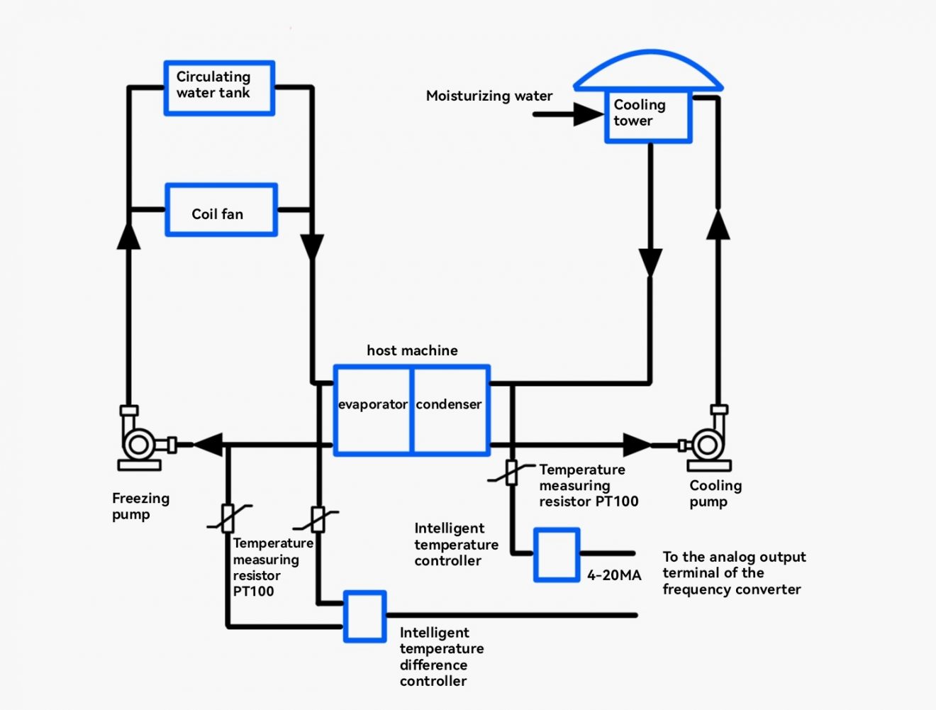
Los sistemas centrales de aire acondicionado se componen principalmente de tres partes principales: la unidad principal, el sistema de circulación de agua refrigerada y el sistema de circulación de agua de refrigeración. En función del tipo de carga, los sistemas centrales de aire acondicionado pueden clasificarse en dos grandes categorías:
Cargas de par constante: Algunos ejemplos son los compresores frigoríficos de tornillo o centrífugos que requieren un par de salida mínimo y presentan una relación casi lineal entre velocidad y potencia.
Cargas de par variable: Algunos ejemplos son los sistemas de circulación de agua de refrigeración, los sistemas de circulación de agua refrigerante (sistemas de circulación de agua de bombas de calor), los sistemas de ventiladores de torres de refrigeración y los sistemas de ventiladores de serpentines. Estas cargas de ventiladores y bombas tienen una relación cúbica entre la potencia del eje y la velocidad, lo que permite un importante ahorro de energía.
Principio de ahorro energético de los compresores frigoríficos
Por ejemplo, en un ciclo de refrigeración por compresión de vapor, el proceso de refrigeración puede regularse utilizando un control de frecuencia variable para ajustar la velocidad del compresor de tornillo. La potencia de salida de un compresor de tornillo puede ajustarse continuamente de 10% a 100%. Los datos muestran que cuando la carga del compresor de tornillo supera los 50%, su potencia es linealmente proporcional a la carga, pero por debajo de 40%, el consumo real de potencia supera los cálculos teóricos. En consecuencia, la tecnología de frecuencia variable no puede conseguir un ahorro energético óptimo en todo el rango de carga, lo que limita su aplicación para la modernización de compresores con fines de ahorro energético.
Principio de ahorro energético de ventiladores y bombas
Según la mecánica de fluidos, el caudal de salida (Q) de los equipos centrífugos de transmisión de fluidos (por ejemplo, bombas centrífugas y ventiladores) es directamente proporcional a su velocidad (n); la presión de salida (P) o altura es proporcional al cuadrado de su velocidad; y la potencia de salida (N) es proporcional al cubo de su velocidad.
Debido a las características únicas de los sistemas centrales de aire acondicionado, deben tenerse en cuenta dos factores: las especificaciones de caudal y altura nominales de la propia bomba y la desviación entre los requisitos reales de presión o diferencial de temperatura de suministro y las especificaciones estándar de la unidad. Por ejemplo, el uso de la recopilación de datos de temperatura en tiempo real y de controladores de temperatura inteligentes para controlar los ajustes del variador de frecuencia puede optimizar el funcionamiento del sistema de bomba de refrigeración y evitar fenómenos como la "bomba muerta" o la "interrupción del flujo".
Condiciones reales del equipo
- Control en bucle cerrado del sistema de bombeo de agua fría (supervisión de la diferencia de temperatura del agua de entrada y de salida)
Los sistemas centrales de aire acondicionado tienen una temperatura estándar del agua refrigerada de 12°C a la entrada y 7°C a la salida, con una diferencia de temperatura permitida de 5°C para el condensador. Si la diferencia de temperatura real es de 2°C, la demanda real de agua fría es de sólo 40% de la capacidad de suministro. En condiciones de frecuencia variable, la velocidad de la bomba sólo necesita funcionar a 40% de la velocidad nominal, reduciendo el consumo de energía a menos de 10% de la energía nominal. Por tanto, hay un importante potencial de ahorro energético.
Para garantizar un caudal suficiente de agua refrigerada al equipo terminal más alejado, debe ajustarse la frecuencia mínima de funcionamiento del inversor de la bomba de agua refrigerada (normalmente 25 Hz), bloqueando la velocidad mínima de la bomba. Un controlador de temperatura inteligente supervisa la diferencia de temperatura del agua refrigerada para controlar la frecuencia del inversor, aumentándola según sea necesario cuando la temperatura del agua de retorno supere el valor establecido.
- Control en bucle cerrado del sistema de bomba de agua fría en modo calefacción (supervisión de la diferencia de temperatura del agua de entrada y de salida)
Este modo es similar al de refrigeración y se aplica durante las operaciones de calefacción (otoño e invierno).
- Control de bucle abierto de la bomba de circulación de agua de refrigeración (supervisión de la diferencia de temperatura del agua de entrada y de salida)
La diferencia de temperatura estándar para la circulación del agua de refrigeración en los sistemas centrales de aire acondicionado es de 4°C a 8°C, y para las torres de refrigeración, de 3°C a 5°C. El sistema consta de bombas de refrigeración, torres de refrigeración y condensadores. En el sistema de circulación del agua de refrigeración influyen tanto las temperaturas ambientales exteriores como las cargas térmicas interiores. Por lo tanto, instalar un sensor de diferencia de temperatura entre las tuberías principales de suministro y retorno es un enfoque racional de ahorro de energía.
En condiciones exteriores estables, una gran diferencia de temperatura indica una elevada carga térmica interior, lo que hace necesario aumentar la velocidad de la bomba de refrigeración para mejorar la circulación. Por el contrario, una diferencia de temperatura menor permite reducir la velocidad de la bomba. Este enfoque puede ahorrar 5-10% más energía que medir únicamente la temperatura del agua de retorno.
Por lo tanto, al evaluar las condiciones reales de funcionamiento, basarse únicamente en la corriente del motor puede llevar a conclusiones erróneas sobre el potencial de ahorro de energía. Es fundamental tener en cuenta los datos operativos reales, como la selección de la capacidad del sistema, los cambios estacionales y las variaciones de carga. La mayoría de los sistemas se desvían de las especificaciones estándar, experimentando a menudo pequeñas diferencias de temperatura, alturas y caudales excesivos. La utilización de la tecnología de frecuencia variable puede ahorrar el exceso de caudal y altura, permitiendo que el sistema funcione de forma eficiente, cumpliendo los requisitos del sistema y minimizando el consumo de energía.
- Control de sistemas de ventilación de serpentines
Cada habitación está equipada con una unidad de ventilador de serpentín (0,40 kW, 220 V) con una diferencia máxima de temperatura del aire de 10 °C a 15 °C (generalmente 8 °C). El sistema de ventilador de batería utiliza agua y aire para transferir el calor de la carga interior, y la mayor parte de la carga de refrigeración o calefacción la gestiona el refrigerante de la batería o el agua del medio calefactor. Los ventiladores satisfacen principalmente las necesidades de ventilación para mejorar el confort de la habitación y gestionar algunas cargas de calefacción o refrigeración.
Originalmente, el funcionamiento del ventilador se controlaba manualmente con un interruptor de tres velocidades, pero se ha implementado el control de frecuencia variable. Tras la modificación, la temperatura ambiente, especialmente en invierno, se mantiene estable en 17 °C ± 1 °C, lo que permite ahorrar una media de 80% de consumo energético en comparación con el funcionamiento a frecuencia fija, lo que equivale a más de 60% de potencia nominal. Además, los niveles de ruido han mejorado considerablemente.
- Control del ventilador de la torre de refrigeración
Los sistemas de torres de refrigeración suelen tener dos ventiladores y funcionan con control de arranque directo a toda velocidad. Ambos ventiladores funcionan a máxima velocidad, por lo que carecen de una detección eficaz del efecto de refrigeración y pierden oportunidades de ahorrar energía en condiciones de refrigeración natural. En particular, durante la primavera, el otoño y el invierno, el control manual no puede responder con prontitud a los cambios de temperatura de salida de la torre de refrigeración, lo que provoca un derroche de energía.
Durante la adaptación, los ventiladores se configuran para arrancar a 35 °C y parar a 30 °C, utilizándose el intervalo de 35 °C a 30 °C para el ajuste de frecuencia basado en el control de volumen variable PID de temperatura. Los resultados de las pruebas muestran que el consumo de energía con el control de volumen variable es aproximadamente 40% del funcionamiento a frecuencia fija, evitando el despilfarro asociado al control manual de arranque-parada. Según datos de reconversiones de aire acondicionado central realizadas con éxito, los sistemas de torres de refrigeración consiguen un ahorro energético superior a 40%, y algunos sistemas con depósitos de torre de refrigeración de gran capacidad ahorran más de 50%.
Características del sistema de ahorro de energía por conversión de frecuencia
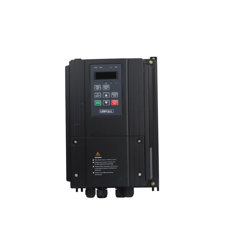
La interfaz del convertidor de frecuencia dispone de pantallas LED con parámetros de control exhaustivos y un diseño sencillo y fácil de usar.
Los sensores de temperatura/diferencial disponen de indicadores LED digitales de doble pantalla que facilitan y simplifican el control de los ajustes de los parámetros de temperatura.
Los convertidores de frecuencia están equipados con protecciones electrónicas de sobrecorriente, sobrecarga, sobretensión y sobrecalentamiento, junto con amplias alarmas de fallo, que protegen eficazmente el sistema de suministro de agua.
La instalación de variadores de frecuencia permite a los motores realizar arranques suaves y ajustes de velocidad continuos, lo que reduce significativamente el desgaste mecánico de bombas y motores y prolonga la vida útil del sistema de tuberías.
El sistema consigue un control de la temperatura en bucle cerrado PID, lo que garantiza cambios suaves de la temperatura interior y mejora enormemente el confort.
Conclusión
La incorporación de un convertidor de frecuenciao variador de frecuencia (VFD), dentro de los sistemas centrales de aire acondicionado marca un avance significativo en la tecnología HVAC. Al adaptar la velocidad de los motores a las fluctuaciones de la demanda, estos sistemas mejoran la eficiencia energética, reducen los costes operativos y prolongan la vida útil de los equipos. A medida que la tecnología sigue evolucionando, el papel de variadores de velocidad en los sistemas de calefacción, ventilación y aire acondicionado (HVAC) está llamada a ser aún más integral para lograr soluciones de climatización sostenibles y eficientes.