Using a frequency inverter or variable frequency drive (VFD) to control multiple motors simultaneously is a common practice in various industrial applications. In such setups, all motors are controlled by the same output frequency of the variable speed drive, theoretically ensuring synchronized speeds. However, due to differences in motor manufacturing and load conditions, discrepancies in actual motor speeds can occur. These differences, if not addressed, can lead to cumulative errors. Below are six critical considerations when using a variable frequency inverter to drive multiple motors.
Note 1: The Power Difference of the Motor Should Not Be Too Large
When using one inverter VFD to drive multiple motors, the power ratings of the motors should be as close as possible, ideally within two power levels of each other. Significant power differences can lead to uneven load distribution, where motors with higher power ratings carry more load, causing imbalance. This imbalance can affect the overall system’s efficiency and may lead to increased wear on the motors. To minimize this risk, select motors with similar power ratings and consider increasing the motor power level by one grade to ensure reliable operation.
Note 2: It Is Best for the Motors to Be Manufactured by the Same Manufacturer
For optimal performance and synchronization, it is advisable to use motors from the same manufacturer, preferably from the same production batch if possible. Motors produced by different manufacturers, or even different batches, may have varying characteristics, such as slip (the difference between the speed of the stator’s rotating magnetic field and the rotor). Using motors with consistent characteristics helps maintain synchronization and reduces the likelihood of cumulative errors, ensuring more uniform load distribution and smoother operation.
Note 3: Fully Consider the Length of the Motor Cable
The length of the motor cables significantly impacts the performance of the variable frequency drive. Longer cables increase the capacitance between the cables themselves and the ground, which can introduce high-frequency capacitive currents due to the high harmonic content in the VFD’s output voltage. These currents can interfere with the VFD’s operation and degrade performance. Therefore, it is crucial to consider the total cable length when planning the installation. Ensure that the combined length of all cables connected to the VFD is within the manufacturer’s recommended limits. If necessary, install output reactors or filters at the VFD’s output to mitigate the effects of long cable runs.
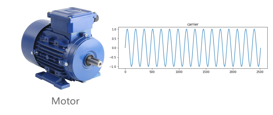
Note 4: The Variable Frequency Drive Can Only Operate in V/F Control Mode
When controlling multiple motors with a single variable frequency inverter, it is essential to use the V/F (voltage/frequency) control mode rather than vector control. V/F control mode is better suited for multi-motor applications as it maintains a constant voltage-to-frequency ratio across all motors, ensuring more uniform speed control. Additionally, the VFD’s rated operating current should be at least 1.2 times the total rated current of all the motors combined. This ensures that the VFD can handle the load without being overstressed, contributing to the longevity of both the VFD and the motors.
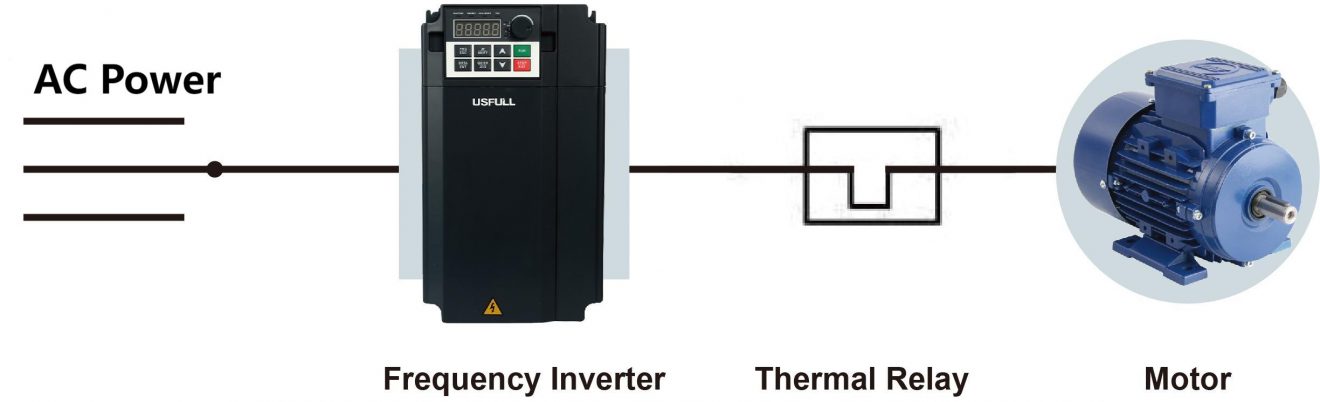
Note 5: In Order to Protect the Motor, A Thermal Relay Should Be Installed in Front of Each Motor
To protect each motor from overheating and potential damage, a thermal relay should be installed in front of each motor. Unlike air circuit breakers, thermal relays provide more precise protection against overloads by detecting excessive current flow due to overheating and disconnecting the motor from the VFD before any damage occurs. This setup prevents the main circuit from being disrupted during VFD operation, ensuring continuous protection for each motor and safeguarding the overall system’s integrity.
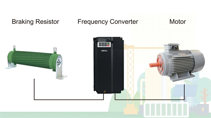
Note 6: Brake Unit and Brake Resistor Should Be Added
For applications requiring rapid deceleration, it is crucial to add a brake unit and brake resistor to the inverter VFD. These components prevent overvoltage during braking by dissipating the excess energy generated when the motors slow down. In some cases, smaller VFDs may come with a built-in brake unit, in which case only an external brake resistor needs to be connected. By including these components, you ensure smoother and safer operation during rapid deceleration, preventing potential damage to the VFD and the motors.
By addressing these six key issues, you can optimize the performance and reliability of your variable frequency drive system when driving multiple motors. Each point highlights critical aspects of system design, helping to prevent common pitfalls and ensuring that your motors operate efficiently and in harmony.