Unexpected VFD low voltage trips can halt your operations, damage equipment, and increase maintenance costs. Fortunately, identifying the root causes and applying smart fixes can ensure stable performance.
Low voltage tripping in a variable frequency drive (VFD) often results from input supply issues or load-side disturbances. Solving this involves voltage stabilization, correct drive selection, and proper installation to avoid costly downtimes.
Understanding what causes these trips—and how to stop them—helps you protect your equipment and investment.
Reasons for Variable Frequency Drive Low Voltage
Low voltage in a variable frequency drive (VFD) typically refers to a drop in the intermediate DC bus voltage, which results from issues on either the power supply side or the load side.
Power Supply Side Issues:
Voltage fluctuations from the utility grid, especially during peak hours, can cause insufficient input voltage.
Transformer overload or poor utility regulation may drop voltage below acceptable levels for the drive.
Line switching, lightning strikes, or other transient disturbances also impact voltage stability.
Long cable runs between power sources and the VFD can create voltage drops, especially under load.
Load Side Issues:
Starting large motors or heavy equipment on the same line can cause a voltage sag.
Sudden torque demands from mechanical loads, like crushers or compressors, can pull voltage down.
Unbalanced three-phase loads also lead to voltage drops in one or more phases, triggering a low-voltage fault.
In both cases, the result is a DC bus voltage below the drive’s acceptable range, which then trips the frequency inverter to protect the system.

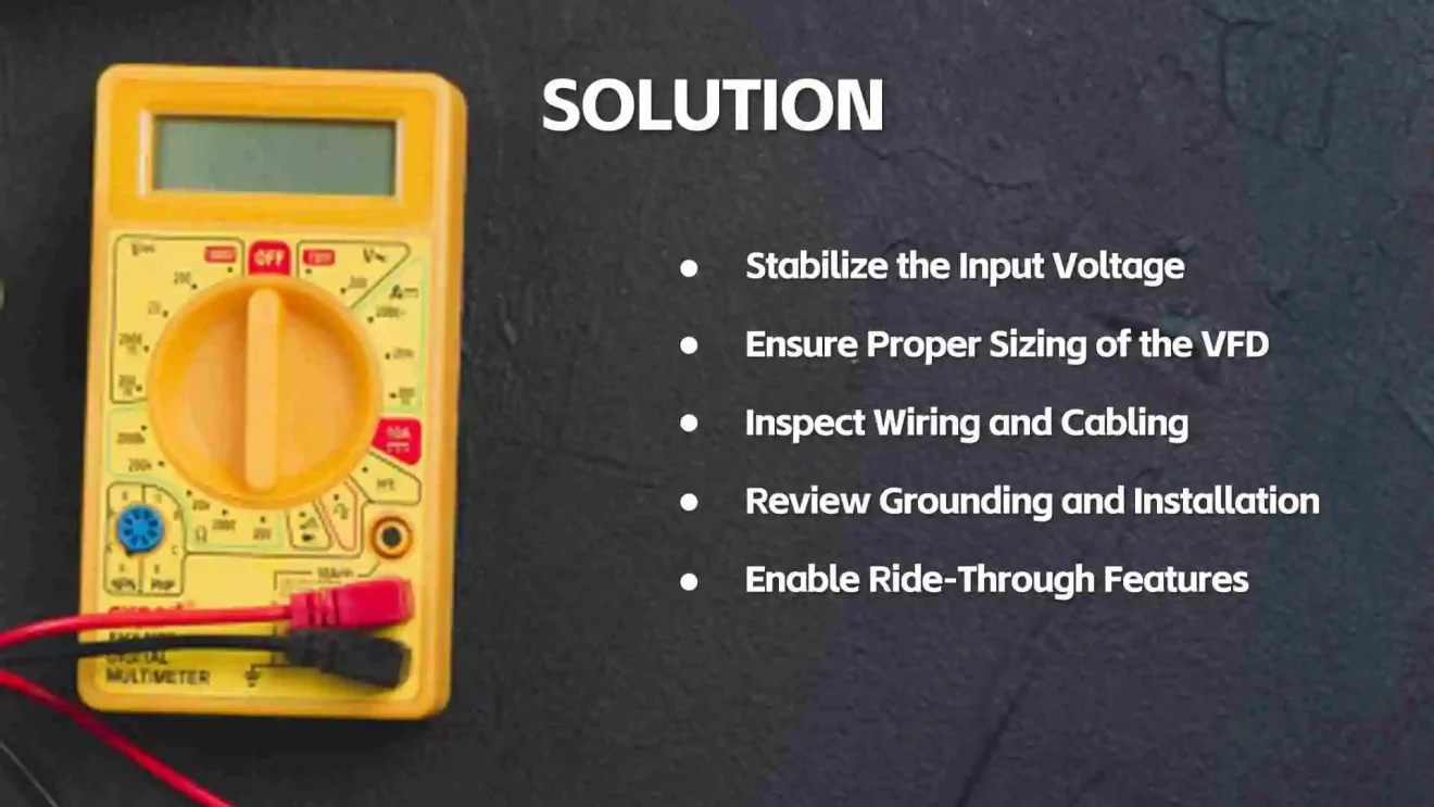
Variable Frequency Drive Low Voltage Tripping Solution
To prevent low voltage tripping, you must address both the power source and the VFD system design. Here’s how:
Stabilize the Input Voltage:
Use a voltage stabilizer, isolation transformer, or uninterruptible power supply (UPS) upstream of the inverter VFD.
Consider adding input reactors or line filters to buffer against voltage spikes or drops.
Ensure Proper Sizing of the VFD:
Choose a variable frequency inverter rated for 10-15% above the motor’s power to withstand occasional voltage sags.
Select VFDs with IGBT-based designs, which handle transient conditions better.
Inspect Wiring and Cabling:
Use appropriately sized, high-quality cables for both input and output connections.
Keep cable lengths within the recommended range and avoid unnecessary splices.
Review Grounding and Installation:
Improper grounding can affect voltage detection and protection circuits.
Make sure your Variable Speed Drive (VSD) is installed in a clean, dry, and cool environment to prevent false tripping due to sensor drift.
Enable Ride-Through Features:
Some modern frequency inverters have low-voltage ride-through or DC bus hold-up features that maintain operation during short sags.
By tackling the issue holistically—voltage source, wiring, load behavior, and drive configuration—you ensure stable and continuous VFD performance.
VFD Overload Tripping Causes and Inspection Methods
Overload tripping is another common issue in VSD systems, often misunderstood as a voltage problem. Here’s how it happens and how to inspect it:
Common Causes:
Motor Overload: If the load is too heavy or jammed, the motor draws excessive current, causing the frequency inverter to trip on overload.
Improper Parameter Settings: Overly tight acceleration or deceleration times force the drive to output more current than rated.
Unbalanced Voltage or Load: A difference in phase voltages can cause the motor to draw uneven current, triggering overload protection.
Ambient Conditions: High ambient temperature or restricted airflow leads to inverter VFD overheating and overload shutdown.
Inspection Methods:
Check Output Current: Compare it to the motor’s rated value. If consistently higher, inspect for mechanical binding or oversizing.
Inspect Motor Temperature: Overheating may indicate continuous overload. Use thermal imaging or temperature sensors for accurate readings.
Review Parameters: Ensure ramp times, max frequency, and torque settings are correctly programmed.
Test Line Balance: Measure voltages across all three phases. Imbalance greater than 2-3% should be addressed.
By regularly inspecting system parameters, motor conditions, and drive settings, you can significantly reduce overload-related interruptions.