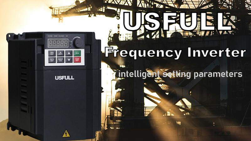
Introduction
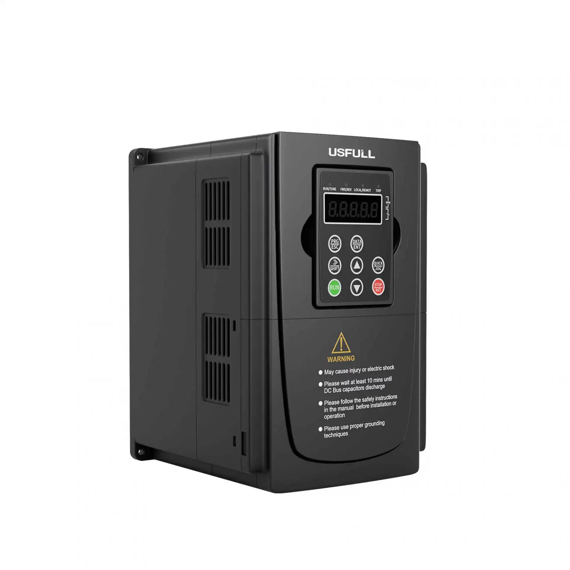
In a frequency inverter control system, several devices are connected to the frequency inverter (also known as a variable frequency drive, variable frequency inverter, or inverter VFD) to ensure optimal performance, protection, and control of the motor. These devices work together to regulate the speed, torque, and direction of the motor, providing efficient and reliable operation in various industrial applications. This article explores the key components typically connected to a variable speed drive within such systems.
Protection and Switching Equipment
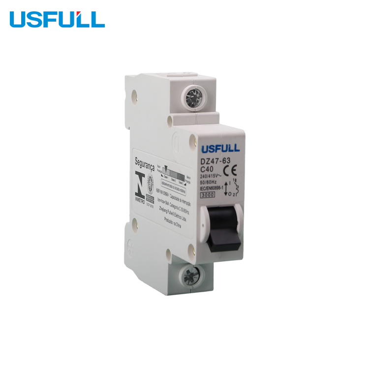
Circuit Breaker
The circuit breaker is a critical safety device that protects the frequency inverter and the overall control system from electrical faults such as short circuits or overloads. Positioned upstream of the frequency inverter, the circuit breaker ensures that any abnormal current is quickly interrupted, preventing damage to the inverter VFD and other connected components.
Electromagnetic Contactor
An electromagnetic contactor is an electrically operated switch used to control high-power electrical devices like motors, lights, and heaters. It works by using an electromagnet (coil) that, when energized, pulls a movable armature to close or open the circuit. The main parts include the coil, contacts, and armature. When power is applied to the coil, it creates a magnetic field that moves the contacts, allowing current to flow. When the coil is de-energized, a spring returns the contacts to their original position, stopping the current flow. It is widely used in industrial applications for remote control of electrical equipment.
Input Side Protection and Filtering Equipment
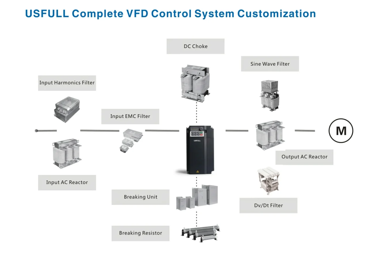
Input AC Reactor
An input AC reactor, also known as a line reactor, is connected to the input side of the frequency inverter. It helps to reduce harmonics generated by the variable frequency drive, improves power factor, and limits inrush currents. This reactor is particularly useful in mitigating the negative effects of high-frequency disturbances on the power supply network.
Input Harmonics Filter
The input harmonics filter is designed to minimize the harmonic distortion caused by the frequency inverter on the power supply. By filtering out these harmonics, the filter ensures compliance with grid standards and reduces the risk of interference with other equipment connected to the same power source.
Input EMC Filter
An input EMC (Electromagnetic Compatibility) filter is used to suppress electromagnetic interference (EMI) generated by the frequency inverter. This filter is crucial for ensuring that the inverter VFD does not interfere with other electronic devices in the vicinity, thereby maintaining a stable and interference-free environment.
Output Side Protection and Filtering Equipment
Sine Wave Filter
The sine wave filter is installed on the output side of the frequency inverter to convert the PWM (Pulse Width Modulation) signal into a near-perfect sine wave. This filtering is essential for applications requiring long cable runs or sensitive motor loads, as it reduces motor heating, noise, and vibration.
Dv/Dt Filter
A Dv/Dt filter is another type of output filter connected to the frequency inverter. It is specifically designed to reduce the rate of voltage rise (Dv/Dt) and limit the peak voltage seen by the motor windings. This protection is vital for motors with long cable runs or those operating in environments with high Dv/Dt stress.
Output AC Reactor
The output AC reactor is connected between the frequency inverter and the motor. Its primary function is to reduce the motor’s peak voltage and the rate of voltage rise (Dv/Dt), which protects the motor insulation and extends its lifespan. It also reduces motor noise and helps in smoother motor operation.
Braking and Energy Feedback Equipment
Braking Unit
The braking unit is an essential component for applications requiring rapid deceleration of the motor. It connects to the DC bus of the frequency inverter and dissipates the regenerative energy produced during braking through an external braking resistor, preventing overvoltage in the DC bus.
Braking Resistor
The braking resistor works in conjunction with the braking unit to safely dissipate the energy generated during the braking process. By converting the excess electrical energy into heat, the braking resistor ensures that the frequency inverter can handle dynamic braking scenarios without damaging the system.
DC Side Equipment
DC Choke
A DC choke is an inductive component connected in series with the DC bus of the frequency inverter. It smooths the DC voltage by filtering out ripple currents and reducing harmonics. This enhances the overall performance and efficiency of the variable frequency drive and protects the inverter from potential electrical stress.
Execution Device
Motor
The motor is the primary load driven by the frequency inverter. The variable speed drive controls the motor’s speed, torque, and direction, making it possible to adapt the motor’s operation to various process requirements. The choice of motor and its proper integration with the frequency inverter are critical for achieving the desired system performance.
Conclusion
In a frequency inverter control system, the integration of various devices like circuit breakers, reactors, filters, braking units, and the motor itself ensures that the system operates efficiently, safely, and reliably. Each component plays a unique role in protecting and optimizing the performance of the variable frequency drive, making them indispensable in modern industrial applications.